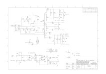
I am working on a Dynaudio BM9s subwoofer that another tech has given up on. It uses a BASH/Buck SMPS power supply. Looking at the schematics, it has what appears to be a somewhat normal SMPS power supply that generates a +40V dc output, and a BASH/Buck converter that takes that +40V and creates -40V. the +/-40V is then fed to a normal Bridged Class AB amplifier.
What is odd is that R111 and R112 are labeled on the schematic as 150 ohm 3 watt. But doing the math, 150 ohms across 40V is nearly 11 watts!!!! and In the unit I am working on the previous tech replaced them presumably because they were burnt up and whatever was used is burnt to a crisp also to the point I have no idea what value was used. I have gone over the unit top to bottom. and cannot find any other signs of damage. just those 2 resistors burnt.
.
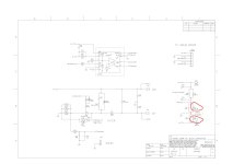
I THINK what they are doing is creating a virtual center tap for a ground reference. and it is labeled as a "Center network"? without those resistors, you get 80V across the CD+ and CD-, BUT, from ground to CD+ you get +80v and almost nothing from CD- so those resistors must being used to center the supplies? and what would a realistic value for them be? If they were 1500 ohms, then they would be dissipating about 1 watt. which using a 3 watt resistor would make sense. But I have no idea what is really happening here.
.
Indigo Designs was based out of canada and seem to now long be defunct. and of course there is no help from Dynaudio. So anyone here familiar with SMPS power supplies, have seen this sort of thing and can help figure out what a correct value for those resistors should be?
Zc
What is odd is that R111 and R112 are labeled on the schematic as 150 ohm 3 watt. But doing the math, 150 ohms across 40V is nearly 11 watts!!!! and In the unit I am working on the previous tech replaced them presumably because they were burnt up and whatever was used is burnt to a crisp also to the point I have no idea what value was used. I have gone over the unit top to bottom. and cannot find any other signs of damage. just those 2 resistors burnt.
.
I THINK what they are doing is creating a virtual center tap for a ground reference. and it is labeled as a "Center network"? without those resistors, you get 80V across the CD+ and CD-, BUT, from ground to CD+ you get +80v and almost nothing from CD- so those resistors must being used to center the supplies? and what would a realistic value for them be? If they were 1500 ohms, then they would be dissipating about 1 watt. which using a 3 watt resistor would make sense. But I have no idea what is really happening here.
.
Indigo Designs was based out of canada and seem to now long be defunct. and of course there is no help from Dynaudio. So anyone here familiar with SMPS power supplies, have seen this sort of thing and can help figure out what a correct value for those resistors should be?
Zc
Attachments
FYI, I used some 1K resistors temporarily and it seems to hold the supplies in balance. I have not yet tried to run an audio signal as I am in the middle of replacing the backup battery in my AP ATS-1. which should be here wed...