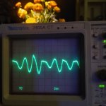
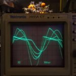
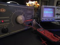
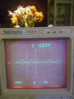
Hello diyAudio forum! I have a vintage Barker & Williamson Audio Oscillator model 200 that I am hoping to restore for this beginner's use on a test bench for learning more about and taking care of my own audio/guitar hobby tube amps . Brought it up on a variac and have connected to a tektronix 2465A oscilloscope to find irregular wave forms. Frequency controls appear to work, but there is pulsing variation in amplitude and shape as shown in the attached images. (I am also a newbie to using an oscilloscope.)
I am hoping knowledge base here can confirm that these symptoms point to either go/no-go decision to restore, and/or to an order of replacing likely causal components. I would replace the capacitors due to their age, but if the varying waveform and amplitude pulse points to other critical parts, I'd like to see if they are available and get a sense of the overall parts cost before investing up front in the caps. There are two (2) quad caps, and about 5 down below. I have not opened the frequency control box behind the big verneer dial!
There's a great video of a unit similar to mine working well, on youtube at:
I have not been able to find a schematic, but I understand (from commenters on the above video) that it may be a licensed version of (the first!?) HP product. Any suggestions for this newbie is greatly appreciated! (This is my first "help" post here!)
I am hoping knowledge base here can confirm that these symptoms point to either go/no-go decision to restore, and/or to an order of replacing likely causal components. I would replace the capacitors due to their age, but if the varying waveform and amplitude pulse points to other critical parts, I'd like to see if they are available and get a sense of the overall parts cost before investing up front in the caps. There are two (2) quad caps, and about 5 down below. I have not opened the frequency control box behind the big verneer dial!
There's a great video of a unit similar to mine working well, on youtube at:
Attachments
I couldn't find a manual for the model 200, but found a manual for the 210. Maybe it will help. Good luck.
http://www.bunkerofdoom.com/lit/bw210_osc.pdf
http://www.bunkerofdoom.com/lit/bw210_osc.pdf

Did you confirm the e-caps and coupling caps were all ok - including leakage currents at rated voltages, and cap values?
Assuming you have a similar circuit to that 210 schematic, if you set output pot to min, then do you get nominal dc voltages on the following valves, including balanced cathode currents for the output stage (with added sense resistors fitted)?
Once you have basic powering and parts ok, then I'd recommend measuring the individual Wien bridge parts and possibly tweaking/padding parts to be exact 2:1 ratios (preferably to better than 1%), as that can be a significant influence on harmonic distortion level.
If the bulb is not original then that could be a major concern.
The web site for the manual seems to have vanished overnight. In any case there should be an adjustment for the feedback to stabilize the oscillator. It looks like its set too high.
Thank you all, for your responses! I have not tested or replaced any capacitors, nor have I tried adjusting either of the two internal adjustment (pots?). I did look at the etching on the lamp and it appears to say 12V 3W. The schematic for the model 210 shows a 120 volt lamp. I'll check the capacitors as best I can, voltages, and see if the oscillator adjustment has an effect.
I'm assuming the variable waveform is "distortion". Am I right? Looks like there is a lot to learn for me in troubleshooting this circuit. May be in over my head. Worth a shot, though, it appears from everyone's input. I'll take some steps forward and report back here. Thanks again!
I'm assuming the variable waveform is "distortion". Am I right? Looks like there is a lot to learn for me in troubleshooting this circuit. May be in over my head. Worth a shot, though, it appears from everyone's input. I'll take some steps forward and report back here. Thanks again!
Trying the proper bulb should be helpful. It is a critical part for proper operation.
https://www.amazon.com/CEC-Industries-3S-6-Bulbs-shape/dp/B00JZ8OYJ6
https://www.amazon.com/CEC-Industries-3S-6-Bulbs-shape/dp/B00JZ8OYJ6