I am a novice. Could you tell me whether this would work or is a nonsense circuit?
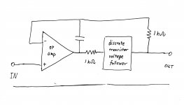
I want to put discrete transistor (bipolar, FET, JFET) voltage follower inside the feedback look of non-inverting OP amp voltage follower(unity gain). I also want RF stability of the voltage follower.
I want to put discrete transistor (bipolar, FET, JFET) voltage follower inside the feedback look of non-inverting OP amp voltage follower(unity gain). I also want RF stability of the voltage follower.
Attachments
Why? For what?
These circuit diagrams seem to ignore the stability issue.
Not necessarily. This kind of buffers are intended to augment the current output capability, not the bandwidth.
> whether this would work
Yes, and it is a common plan.
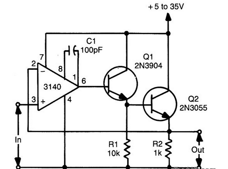
Say C is 0.01uFd against R=1K. Then up to 15KHz the opamp controls the follower; past 15KHz the opamp controls itself and is not much affected by the follower's phase shift. Typically we can build a better follower and (for R=1K) C may be 470pFd, 300KHz crossover.
Stability is still not ensured, because there are many ways any amplifier can oscillate.
Yes, and it is a common plan.
Say C is 0.01uFd against R=1K. Then up to 15KHz the opamp controls the follower; past 15KHz the opamp controls itself and is not much affected by the follower's phase shift. Typically we can build a better follower and (for R=1K) C may be 470pFd, 300KHz crossover.
Stability is still not ensured, because there are many ways any amplifier can oscillate.
Yes the circuit of post#1 can be made to work. However the circuit designer does need to know the worst case load that will ever be attached, in order to make a design with guaranteed stability and reliability.
If the load is resistor, why would it be unstable?
The bandwidth of EF is normally faster than op amp, shouldn't be any problem.
Maybe when the op amp has large output resistance and transistor has large capacitance on input.
I'm thinking about this kind of circuit with rail-to-rail output Op amp, when the output impedance is changing through frequency, I don't know how to analyze stability .
If it's an audio power amplifier it might be called upon to drive a 3-way loudspeaker with a crossover network, which is a reactive (not resistive) load. Or it might be used to drive a planar loudspeaker, which is a capacitive (not resistive) load. Capacitive loads are especially challenging to the stability of an amplifier with negative feedback.
True, my thought stopped at cable capacitance. and when I simulate, I do only 1 nf Cap. Thankx for the reminder.
> whether this would work
Say C is 0.01uFd against R=1K. Then up to 15KHz the opamp controls the follower; past 15KHz the opamp controls itself and is not much affected by the follower's phase shift. Typically we can build a better follower and (for R=1K) C may be 470pFd, 300KHz crossover.
/QUOTE]
So it acts as a low pass filter in the loop, to isolate phase shift?? Such a awesome trick. There're 2 transistors, i'm wondering if those 2 have to be the same value.
Resistor at input of follower is irrelevant and often not needed.
You're awesome, thank you. Bcs I was thinking that resistor might form another pole with transistor's input capacitance, that wouldn't be fun to play with.
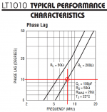
There's a reason why IC manufacturer's datasheets of Unity Gain Buffer Amplifiers (fancy emitter followers) include a graph of Phase Lag vs frequency vs load. It helps the circuit designer / customer decide whether or not his composite (opamp + Unity Gain Buffer) will be adequately stable.
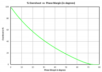
For example, if you proposed to connect an opamp whose GBW is 7.5 MHz and whose phase margin at 7.5 MHz is 60 degrees, in cascade with an LT1010 Unity Gain Buffer IC (datasheet figure below), driving (200 ohms || 100pF), the composite would have (60 - 10) = 50 degrees of phase margin. That's just barely stable, and its transient response will overshoot by 18%, which some engineers would consider unacceptable.
_
Attachments
- Status
- Not open for further replies.
- Home
- Source & Line
- Analog Line Level
- bandwidth limiting non-inverting follower