On the subject of bandpass enclosure design - standard methodology usually prescribes a front chamber tuning frequency that is closely related to the speaker+rear chamber alignment (whether sealed/4th order or vented/6th order). I am trying to get information on when and how it makes sense to attempt to tune the front chamber to a substantially different and higher frequency. The objective would be to create an enclosure with a bandwidth that is much wider than the typical standard bandpass configuration (say 30Hz - 300Hz), but one which does not create misalignments that would degrade the transient response.
Is there a methodology to do this that someone could refer me to?
Many thanks - Ram
Is there a methodology to do this that someone could refer me to?
Many thanks - Ram
Last edited:
In normal life - outside the world of web-based woofer sims - people start by prioritizing their purposes.
Are you playing music for which good transient response (or whatever is the psychoacoustic parameter) is essential for your enjoyment? Do you want to optimize, satisfize, or maximize it?
If you want to focus on transient response, you need to identify good candidates in drivers, electronics/crossovers, and enclosures. Then proceed to design.
Of course, that should lead you to motional feedback and sealed boxes.
Ben
maybe not quite a real BP - vent is like the famous R-J - I used 4 of these 18s back in the day- - the aperture could be truncated
An externally hosted image should be here but it was not working when we last tested it.
How about tuning the bandpass for the typical flat 2 octave response (75hz to 300hz) and EQing the bottom end (sealed rear)
OR
port the rear chamber near 30hz to reduce excursion of driver and then EQ for the target response (ported rear)
OR
port the rear chamber near 30hz to reduce excursion of driver and then EQ for the target response (ported rear)
Last edited:
Let me sharpen the discussion a bit by referring to the sealed rear chamber bandpass design tables in Vance Dickason's book. If I choose S = 0.7 which has the best transient response, and a peaking factor of 0dB, then I get a fH:FL factor of 1.16:0.43. Note that this has nothing to do with driver parameters. It appears that one cannot arbitrarily choose an fH if you go with this methodology. Based on this you will see that with most drivers you will find it hard to get a bandwidth of even 30-100Hz, let alone 300Hz.
- Yes one needs to choose good drivers, electronics etc, but as always I am looking at just the enclosure and asking if what I seek is feasible at all within the boundaries of "good enclosure design". Further, I would say I do not mind what word is used to describe the transient response objective (optimize, satisfize, or maximize) as long as it is positive and not negative.
- I am also not concerned about efficiency - I just want to know if there exists a methodology to produce good alignments with higher tuning frequencies for the front chamber.
- A simulation would be done but not before starting with a design methodology. For example, Dickason's book is a methodology that gets you to something that you simulate. Simulation without a methodology is as bad as pure trial and error.
Thanks for your responses!
-Ram
If the intended use is for home then the alignments are only of theoretical interest. The response is dictated by room and that too very strongly. The alignments are free field responses and not room responses.
If I understand correctly then you are seeking 30hz to 300hz bandwidth. Bandpass's typically give 2 or 2.5 octaves only. It would be worth simulating the responses and then see how it turns out.
If I understand correctly then you are seeking 30hz to 300hz bandwidth. Bandpass's typically give 2 or 2.5 octaves only. It would be worth simulating the responses and then see how it turns out.
Further, I would say I do not mind what word is used to describe the transient response objective (optimize, satisfize, or maximize) as long as it is positive and not negative.
-Ram
You just take Qes and multiply it by the square root of minus one. That produces Ti, tthe imaginary transient response.
I think Voltaire did a good job of characterizing the issues that arise when the adherents of theory adhere too much. Which I think represents the import of a number of posts so far.
Ben
Last edited:
Ram,Further, I would say I do not mind what word is used to describe the transient response objective (optimize, satisfize, or maximize) as long as it is positive and not negative.
- I am also not concerned about efficiency - I just want to know if there exists a methodology to produce good alignments with higher tuning frequencies for the front chamber.
If you are not concerned about efficiency, I'd suggest using a sealed, ported or tapped horn alignment, as the rapid phase change in the upper end of the bandpass is (usually) difficult to integrate with the phase response of the top cabinets, resulting in a (choose your adjective) muddy, murky, or "lack of punch" response character in the crossover region.
At least that has been the case with every BP cabinet I have heard (or built) thus far.
Art
I can confirm that.Ram,
If you are not concerned about efficiency, I'd suggest using a sealed, ported or tapped horn alignment, as the rapid phase change in the upper end of the bandpass is (usually) difficult to integrate with the phase response of the top cabinets, resulting in a (choose your adjective) muddy, murky, or "lack of punch" response character in the crossover region.
At least that has been the case with every BP cabinet I have heard (or built) thus far.
Art
BP4 has better transient response than BP6A or BP6B in my experience, but I don't think that kind of bandwidth is possible.
BP4 has better transient response than BP6A or BP6B in my experience, but I don't think that kind of bandwidth is possible.
A 4th order BP alignment with a wide bandwidth - isn't that a front-loaded horn? (GD&R.. 🙂)
Thanks for your constructive suggestions 🙂. Will look in the direction of a horn alignment as suggested.
I am reminded of a little 1952 gem by Lewin, more than reasonably applicable to speaker design, that is worth mulling over : "There is nothing more practical than a really good theory".
Any more constructive suggestions, please contribute!
Thanks again.
Best - Ram
I am reminded of a little 1952 gem by Lewin, more than reasonably applicable to speaker design, that is worth mulling over : "There is nothing more practical than a really good theory".
Any more constructive suggestions, please contribute!
Thanks again.
Best - Ram
Not really, I had written this earlier..........
Hmm...... a 'typical' BP would be 30-120 Hz or up to 240 Hz at most, but 30-300 Hz would be a high CR horn, so not typical and wider would require typical point source drivers with 'unobtanium' specs.
..........but DJK, Brian had already posted it by the time I got back on line.
That said, use the late Prof. Leach's horn math to either calculate the driver specs required to make a specific horn or what viable horn alignments are practical with a given set of driver specs, then use Hornresp
or similar to sim them.
Or do as most and try different drivers in HR to get a default alignment and use the Wizard tool to 'slide' your way to different sizes, shapes, compression ratios [CR], etc., with the understanding that many drivers can't handle > 1:1 CRs at rated power unless they have strong [low Qts] motors and tight [low Vas] suspensions.
GM
Let me sharpen the discussion a bit by referring to the sealed rear chamber bandpass design tables in Vance Dickason's book. If I choose S = 0.7 which has the best transient response, and a peaking factor of 0dB, then I get a fH:FL factor of 1.16:0.43.
Qt
GM
Ram,Thanks for your constructive suggestions 🙂. Will look in the direction of a horn alignment as suggested.
Although bass horns are pretty much omnidirectional below 100 Hz, they are usually quite directional if used as high as 300 Hz, causing imaging problems unless the mains are also designed to have similar dispersion at the crossover point, and the mains are co-located with the horn exit.
For a FLH to hit 30 Hz, the path length must be 9.4 feet long, and the mouth needs to be rather large, like a corner of a room size. Corner horns can be a good idea, but may not work well for your particular room or main speakers.
TH don't require large exit size, so are generally more user friendly, but are limited to about 3 octaves of (good sounding) bandwidth.
Art
Hi,
Kef did it in a number of their designs, though only up to 200Hz or so.
Note the highpass cannot be expected to be textbook smooth,
Kef used additional filtering to hit 4th order targets.
See below for where Lewin disingenuously nicked his quote from.
I guess those in Lewin's field don't read thermodynamics papers.
rgds, sreten.
Last edited:
Akabak script for 6th order series band pass
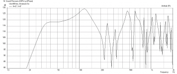
It is quite easy to model this and try adjusting the front/rear chambers and vent dia x lengths to optimize what you are looking for. 30Hz to 300Hz is kind of large - probably beyond the capability of a band pass box. Here is a sample script for a 6th order series band pass. It is simple and possible with 9 lines of code. Very powerful and very easy to use once you have sample scripts to work with.
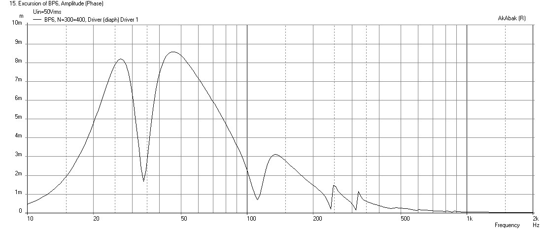
Here are the results from the above Akabak script...
FR:

Displacement:
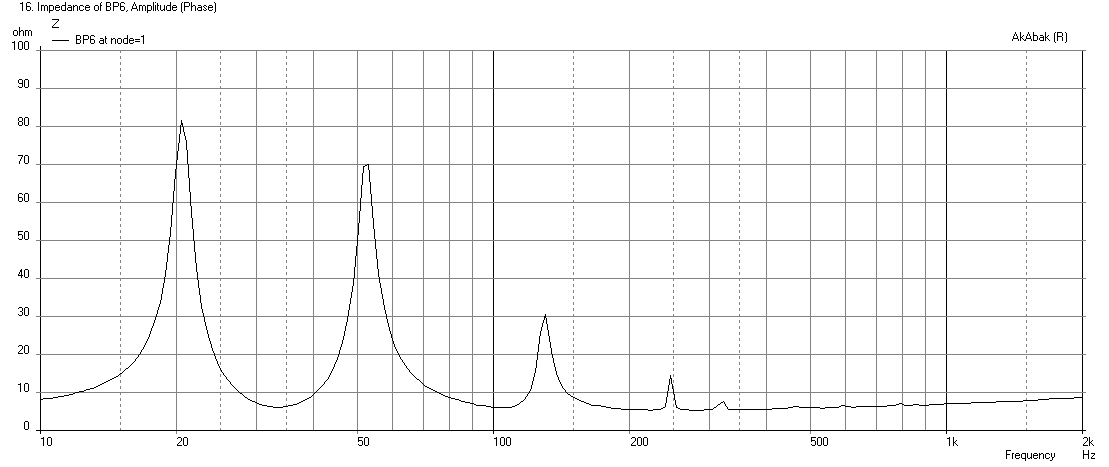
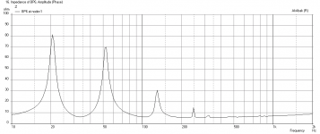
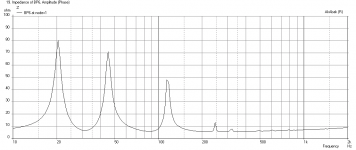
Impedance:
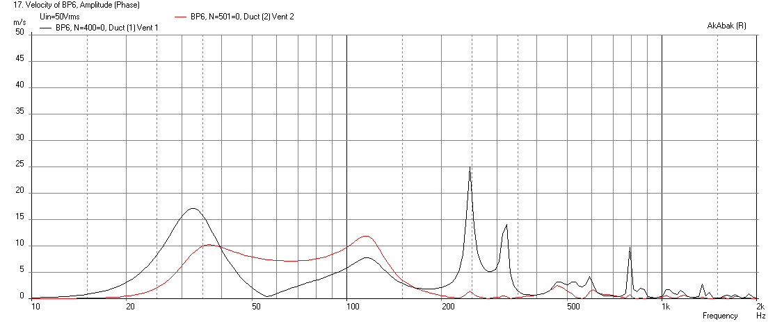
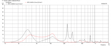
Duct Velocities:
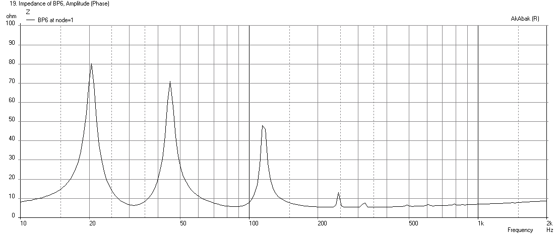
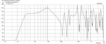
Here is the effect of making the second vent twice as long (16in vs 8in):

And you can see what that did to the Impedance and tuning frequencies by location of impedance minima:
It is quite easy to model this and try adjusting the front/rear chambers and vent dia x lengths to optimize what you are looking for. 30Hz to 300Hz is kind of large - probably beyond the capability of a band pass box. Here is a sample script for a 6th order series band pass. It is simple and possible with 9 lines of code. Very powerful and very easy to use once you have sample scripts to work with.
Code:
System 'BP6' | 6th order band pass script by xrk971, Apr 30,  2015

Def_Driver 'BC15TBX40'  Sd=862cm2 Bl=24.6Tm Qms=6.3 Qes=0.29 Mms=141g fs=38Hz Vas=131L Le=1.8mH Re=5.2ohm | TS params here

Filter    'High Pass' fo=30.5Hz  vo=1.0  {b4=1;  a4=1;  a3=2.613126;  a2=3.414214;  a1=2.613126;  a0=1;  }  | 4th order BW HPF

Driver Def='BC15TBX40' 'Driver 1' Node=1=0=300=400  | connect driver here node 1=amp, 0=GND, 300=front cone face, 400=rear cone face

Enclosure  'Back Chamber'  Node=400  Vb=67L  Qb/fo=0.707  Lb=24in  | Chamber 1 node 400

Duct    'Vent 1'  Node=400=300    wD=18in hD=2in Len=25in  | Vent 1 between chamber 1 and 2

Enclosure  'Front Chamber'  Node=300  Vb=33L  Qb/fo=0.707  Lb=12in  | Chamber 2 node 300

Duct 'Vent 2'  Node=300=501  dD=10in  Len=8.0in  | Vent from chamber 2 to outside

Radiator 'Duct Rad1' Def='Vent 2' Node=501 Label=20  | Radiator element on vent 2
Here are the results from the above Akabak script...
FR:
Displacement:
Impedance:
Duct Velocities:
Here is the effect of making the second vent twice as long (16in vs 8in):
And you can see what that did to the Impedance and tuning frequencies by location of impedance minima:
Attachments

Last edited:
- Status
- Not open for further replies.
- Home
- Loudspeakers
- Subwoofers
- Bandpass enclosure - independent front chamber tuning?