As already suggested, try it unballanced to the xover and see if it works, it will probably be fine. Fix the problem if there is one, changing things risks damage.
Vestax *already* designed a fix. The PCM-05 Pro IV...But I like a known-good factory-thought-out plan.
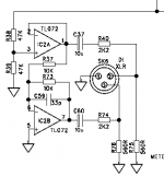
PRR, perhaps my eyes deceive me, but aren't those op-amp inputs incorrectly reversed? As drawn, the feedback networks loop back to the non-inverting inputs rather than the inverting. Also, the Hot and Cold lines to the XLRs would swing in-phase, rather than the correct anti-phase. Must be a drafting error.
Sorry, can´t draw so for now cut and paste only.
Later will show a single supply version if needed, please confirm internal voltages available.
This is the real thing, just needs slicht supply/biasing conversion .
IC2a straight drives XLR pin 2, IC2b inverts that and drives XLR pin 3
Circuit includes unnecessary (for you) attenuation but is what appeared first, next will be better 🙂
And much simpler.
You can build it on a thumbnail sized perfboard or similar.
Attachments
So? 🙄Vestax MW-3000. The service manual is on that site!
You are asking so you download and post it here 😀
I'm a little late, but from the view of a live audio tech of over 40 years.
Active: Measures better
Transformer: Sounds better
I know that the transformer is not technically correct, but it sure can solve a lot of problems. Sometimes it feels like it's working magic. For decades I've kept a pair of 1:1 transformers on hand to isolate front of house from the PA. It can cure the most mysterious of problems. Currently I use Cinemag, but Jensen are good too.
As stated in the posts above, if the cable run is not too long and the environment is not too electrically noisy - try the unbalanced connections. Just remember that a set of good tranfos can cure all sorts of headaches.
Pretty sure Ken Newton is correct -- every dual 8-pin op amp I've seen has the outputs on 1 and 7, '-' inputs next to 'em on 2 and 6, '+'s on pins 3 and 5. Of course, both my brain and eyesight are well past their prime ...
The best place to add a transformer is not at your output but rather at the input of the receiving device. In this case you want an input transformer. Jensen makes some really great ones with proper shielding. However, that is often impractical in which case an output transformer is what you want.
I have run tests with the folks at Jensen comparing electrically balanced and transformer balanced circuits. Below 3-5 kHz the transformer is king. It offers a higher impedance to ground and this helps your CMRR. However, above 5k internal capacitance within the transformer create a slight imbalance. This reduces CMRR at those frequencies. So the way to go really depends on the type of problem you are worried about. For hum issues, go with a transformer. For hiss issues go with electrical balancing.
I have run tests with the folks at Jensen comparing electrically balanced and transformer balanced circuits. Below 3-5 kHz the transformer is king. It offers a higher impedance to ground and this helps your CMRR. However, above 5k internal capacitance within the transformer create a slight imbalance. This reduces CMRR at those frequencies. So the way to go really depends on the type of problem you are worried about. For hum issues, go with a transformer. For hiss issues go with electrical balancing.
Douglas Self proposed a way to lower the distortion of a transformer, using an op-amp circuit having a negative resistance ouput (Small Signal Audio Design, 2nd edition, page 555). The question : would you prefer this configuration compared to a transformer simply driven by a low impedance as usual ?I'm a little late, but from the view of a live audio tech of over 40 years.
Active: Measures better
Transformer: Sounds better
I know that the transformer is not technically correct, but it sure can solve a lot of problems. Sometimes it feels like it's working magic.
PRR, perhaps my eyes deceive me, but aren't those op-amp inputs incorrectly reversed? As drawn, the feedback networks loop back to the non-inverting inputs rather than the inverting. Also, the Hot and Cold lines to the XLRs would swing in-phase, rather than the correct anti-phase. Must be a drafting error.
Schematic is indeed in error. As drawn the opamp acts as a comparator generating square wave full-swing output.
I would use only a transformer on high end gear or as a measure for preventing hum.
Most of DJ mixers are electronic balanced and the cheaper ones are impedance balanced.
Cold is tied to ground with a resistor with the same impedance as the hot.
Balanced lines don't care if there is sound on both wires. Equal Impedance is what matters, but of course You will have half the level compared with a dual op-amp stage.
That schematic has the op amp feedback going to the non inverting inputs...While the Jensen AN003 plan works, it does not increase signal swing, and that DJ mixer appears to run on rather low supply voltage.
Vestax *already* designed a fix. The PCM-05 Pro IV has the unbalanced output main board, and another board to balance the output (and double the max output on the same supply), AND protects it against 48V Phantom (a real risk when sending XLR cable to strange soundmen). There's other ways to do all this, sure. But I like a known-good factory-thought-out plan.
Oh, that's not necessary. You would have to wire the circuit as follows:Vestax comes with basic 15v dc wall adapter. I'd like to use it for everything and not have extra supplies.
Any recommendations on how to convert to +/-15v to power the balancing circuit? Compact, ready made kits available?
(mixer) --> (circuit)
VCC --> V+
1/2VCC --> ground
Power ground --> V-
Avoid unduly loading 1/2VCC, but with just a -1 gain amplifier and maybe a unity gain buffer this shouldn't be an issue anyway.
Let us know when you have a candidate for a schematic.
I am sure there would be room for further tweaks, but the legibility of the schematic makes identifying them rather difficult.
It's been years since I did professional audio but back then we wired balanced to unbalanced all the time, rarely using transformers or buffer circuits. You just have to test what works, usually tie -ve in to ground at the source, the point where they are the same anyway. There are a couple ways to get it wrong but you just need to test it. The worst problem is connecting balanced out to an unbalanced in, which may or may not require leaving the -ve out open.
I am ordering this assembled board. I think it meets my needs:
Addon BalOut v2 – Balanced output board – nihtila.com
All I need now is to get +/-15v dc from a 15vdc supply line going into this mixer. Suggestions for a device that will convert?
Addon BalOut v2 – Balanced output board – nihtila.com
All I need now is to get +/-15v dc from a 15vdc supply line going into this mixer. Suggestions for a device that will convert?
2.0A or 2.0B?I am ordering this assembled board. I think it meets my needs:
Addon BalOut v2 – Balanced output board – nihtila.com
Actually you'd need little more than a little synchronous buck regulator wired up as an inverter to generate -12V from the existing regulated +12V. Chips are typically using internal switched capacitor jobs for this, avoiding external inductors.All I need now is to get +/-15v dc from a 15vdc supply line going into this mixer. Suggestions for a device that will convert?
You only need a whopping 11 mA (or maybe 22), but the thing would have to be rated for an input voltage of at least 24 V, which is about the only bigger drawback of inverting operation. Not sure what to use, even an LM2596 seems massively oversized here - I'd be aiming for maybe 100-500 mA, which often pushes the switching frequency into the MHz range as well, making filtering quite easy (and you do want both common-mode and differential mode chokes on your input and output to avoid nasty surprises).
That said, the LM4562 is spec'd from +/-2.5 V up, so a +12 V supply would be easily workable for them, and the pull-down resistor is low enough that latchup should not be an issue. The Addon BalOut board has the wrong kind of supply bypassing for single supply operation though (which should be V+ to V- rather than V+ and V- to GND), plus external coupling caps and input pull-down resistors would be required. Might still be easier and cheaper than the DC/DC route though.
One thing I'm not sure about with this board is what it does with input ground. Does it really connect input ground and supply ground together? Once installed, that would be an internal ground loop right there.
- Status
- Not open for further replies.
- Home
- Live Sound
- PA Systems
- Balancing the outputs: transformer or electronic?