Has anyone successfully implemented something similar to the attached schematic.
I've sim'd with the following values:
C1, C2 = 0.5uF
R6, R7 = 18K
R9 = 82K
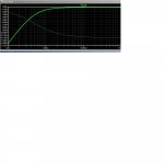
The response is essentially flat to 10Hz and 6dB down at about 2Hz.
This approach has the potential for stability problems but with careful selection of values it should be possible to make it work.
The advantage is a much smaller inpuT cap as well as partial distortion cancellation.
I've sim'd with the following values:
C1, C2 = 0.5uF
R6, R7 = 18K
R9 = 82K
The response is essentially flat to 10Hz and 6dB down at about 2Hz.
This approach has the potential for stability problems but with careful selection of values it should be possible to make it work.
The advantage is a much smaller inpuT cap as well as partial distortion cancellation.
Attachments


- Status
- Not open for further replies.