I'm doing a little project intended mostly to utilise the parts I have in my drawer. It is a fully differential PP amp with the phase-splitting input transformer. And I need the volume control for it.
The most sane way is obviously to use the dual pot after the transformer, one gang for each secondary half. The problem is this is stereo amp, so I'll need the quad pot - and I don't have one of the appropriate value at hand.
I do have a selection of dual pots though, so I'd like to have a solution that uses one gang per channel. Two options come to mind - installing the pot before the transformer as the usual attenuator, or using the shunt configuration (with two constant resistors) at the secondary side. Unfortunately, both those methods make for source or load impedance varying with volume, and transformers don't really like that.
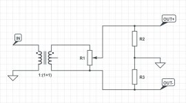
I came up with another method that seems pretty obvious to me (schematics attached), but somehow I haven't found anyone using it, apart from somewhat similar idea from the Sowter 9335 application notes (example #2) which uses multitapped secondary itself instead of the pot.
Are there some potential issues with my idea I'm unaware of? Dissimilar output impedances, unexpected phase shifts, stuff like that?
Thanks in advance!
The most sane way is obviously to use the dual pot after the transformer, one gang for each secondary half. The problem is this is stereo amp, so I'll need the quad pot - and I don't have one of the appropriate value at hand.
I do have a selection of dual pots though, so I'd like to have a solution that uses one gang per channel. Two options come to mind - installing the pot before the transformer as the usual attenuator, or using the shunt configuration (with two constant resistors) at the secondary side. Unfortunately, both those methods make for source or load impedance varying with volume, and transformers don't really like that.
I came up with another method that seems pretty obvious to me (schematics attached), but somehow I haven't found anyone using it, apart from somewhat similar idea from the Sowter 9335 application notes (example #2) which uses multitapped secondary itself instead of the pot.
Are there some potential issues with my idea I'm unaware of? Dissimilar output impedances, unexpected phase shifts, stuff like that?
Thanks in advance!
Attachments
This will work, but the circuit will no longer be balanced.
As you probably know, balanced means both sides having equal impedances, so that any interference will be equal on both sides and cancelled at the balanced receiver.
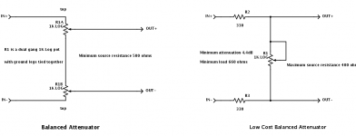
If you want to make it fully balanced, take two resistors from each output of the transformer to the top and bottom of the pot. Use the pot as variable resistance, between them. The balanced output of that circuit is from the top and bottom of the pot.
Jan
As you probably know, balanced means both sides having equal impedances, so that any interference will be equal on both sides and cancelled at the balanced receiver.
If you want to make it fully balanced, take two resistors from each output of the transformer to the top and bottom of the pot. Use the pot as variable resistance, between them. The balanced output of that circuit is from the top and bottom of the pot.
Jan
I do know that, but I don't need it to be "textbook balanced". This isn't for driving long cables, where high CMRR is needed. I just want "reasonably good phase splitting".As you probably know, balanced means both sides having equal impedances, so that any interference will be equal on both sides and cancelled at the balanced receiver.
Highly dissimilar output impedances might cause problems at HF though, given that this thing has to drive some input capacitances. How can I calculate the output impedances for each output in this case?
That's the shunt configuration I've mentioned before, and it has some serious drawbacks like the varying load impedance and signal attenuation even at max volume position.If you want to make it fully balanced, take two resistors from each output of the transformer to the top and bottom of the pot. Use the pot as variable resistance, between them. The balanced output of that circuit is from the top and bottom of the pot.
Yes, the fully balanced has some drawbacks, it balances some attenuation) which is easily made up for by some extra gain or just by turning the pot up a bit more) against EMI sensitivity. I'm not sure why varying load impedance would be an issue?
But note, what you get instead is unbalanced source impedance seen by the receiving side. Whether that is an issue depends on that circuit which is not shown.
But if EMI is not your concern, the single pot like you show will work fine, even if it negates the balanced source advantages.
You pick your poison.
Jan.
Last edited:
Some transformers (mine in particular) are pretty sensitive to load impedance in terms of frequency responce, especially at HF. I get about 1.5dB difference at 30kHz going from 50k to 100k load.I'm not sure why varying load impedance would be an issue?
Just the differential triode stage, fully symmetrical (equal input capacitances)But note, what you get instead is unbalanced source impedance seen by the receiving side. Whether that is an issue depends on that circuit which is not shown.
Thank you!But if EMI is not your concern, the single pot like you show will work fine, even if it negates the balanced source advantages.
You didn't read my post very carefully, did you? 😀I usually use this circuit.
Depend where the connection to the other device is located.Are there some potential issues with my idea I'm unaware of? Dissimilar output impedances, unexpected phase shifts, stuff like that?
Mona
Attachments
Both the transformer and the pot are at the receiving end, directly at the amp's input.Depend where the connection to the other device is located.
Thanks!
If you drive a tube like 12AT7 you need to have high resistance pot (500k+) and like 470k resistors. The xformer works the best (higher level, lower bass) with low output current. The pot already doubles the current, so the high value.is needed.
Since the elevated anode has a resistor to the gate there might be a DC current through the winding, which is deadly even when small, so 2x 10n between pot and resistors.
Even then the output will not be exactly identical, but you can tune the Cathode resistor.
Since the elevated anode has a resistor to the gate there might be a DC current through the winding, which is deadly even when small, so 2x 10n between pot and resistors.
Even then the output will not be exactly identical, but you can tune the Cathode resistor.
My particular transformers work happily with 50k load (full secondary), providing flat (-0.1/+0dB) response in the 10Hz-30kHz range. But since the input impedance is basically 1/4 of pot's value (as long as R2 and R3 are large enough), I might use 100k pot - 12.5k impedance is a bit low for some of my sources, 25k is better.If you drive a tube like 12AT7 you need to have high resistance pot (500k+) and like 470k resistors. The xformer works the best (higher level, lower bass) with low output current. The pot already doubles the current, so the high value.is needed.
I didn't quite get this part. It is intended to drive two triode grids which are at the ground level (self bias). Where the DC current comes from?Since the elevated anode has a resistor to the gate there might be a DC current through the winding, which is deadly even when small, so 2x 10n between pot and resistors.
Even then the output will not be exactly identical, but you can tune the Cathode resistor.
Indeed i missed something...
But if the attenuation is at the input side it can be used this way. Choose higher value resistors. You could terminate first with a lower value resistor to match impedance. Then the resistor netwerk after the termination have miner infuence.
What transformer are you using?
But if the attenuation is at the input side it can be used this way. Choose higher value resistors. You could terminate first with a lower value resistor to match impedance. Then the resistor netwerk after the termination have miner infuence.
What transformer are you using?
Those are Joyin Audio 10k:40k. Cheap Chinese stuff (I've paid like $40 for a shielded pair on a PCB), but they actually measure really flat with 20-100k load over the secondary and small series resistor in the primary (several kOhms depending on the secondary load).What transformer are you using?
The thing is this series resistor is kinda critical - double or half it, and the perfect frequency response goes down the drain.
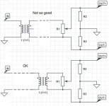
If you do not use any ground tap then a simple pot is possible and still have 100% balance. However you will need to have grid leak resistors as was suggested... (the value of R2 and R3 need to be very high)
Last edited:
100k pot and 2x470k (or 50k and 2x220-330k) should be quite enough. R2 and R3 are the grid leak resistors.
Well, I did some breadboarding today, and I guess I know now why no one uses this solution.
Without any secondary tap being directly grounded, it picks all sorts of EMI crap it could find around 🙁
The impedance is just too high, so even the tiniest induced current results in huge induced voltage.
Without any secondary tap being directly grounded, it picks all sorts of EMI crap it could find around 🙁
The impedance is just too high, so even the tiniest induced current results in huge induced voltage.
- Home
- Amplifiers
- Tubes / Valves
- Balanced volume control with a single pot?