Forgive the dreadful drawing!!
So what I tried to do here is show the two stages I built. On the left is my 'instrumentation amp' which I am hoping will operate as a balanced line receiver. So in balanced mode, my hot output goes to Vin+ and the cold output goes to Vin- . The two input IC's are the two halves of an INA2134 and with the resistors I used, I think the gain of this bit is =2. The differential amp is an INA137 with a gain of 1/2 so overall my 'receiver' has an overall gain of close to 1.
I have not tested this with a balanced input yet. BUT......
I did test this with the guitar (listening at Vout so without the 'buffer' cct that I have also drawn) and connected my TR cable tip to Vin+ and the Vin- to ground. So not a balanced cct obviously. And it sounds great!
The attenuation and 'muddiness' is gone and in fact I get a nice 'buffered' tone. Not surprising I guess, since I now have a nice high-Z input!
The circuit drives all my pedals so responds well and drives loads with varying input impedances of their own. So all good so far.
The buffer cct I have drawn was not used in these tests, to this point as I say, but sounded very good when I did add it after the 'receiver'
So I guess my question now becomes, do you think my 'receiver' circuit will cut it as a balanced line receiver when I do plug a balanced input into it or have I in someway compromised the whole thing? Assuming the answer is that it will function as a basic balanced receiver, does anyone have any suggested improvements?
Zero D thank you for your circuit btw. What you are drawing of course makes sense, but my goal is to have a single jack device with no manual switches.
So if I plug in a TRS lead from a balanced output, I get the benefits of a balanced receiver, and if I plug in a TR cable firect from the guitar, then ok it is not balanced, but I basically get a gain=1 signal out of the receiver. (and if fact a bit of a buffer based on the fact that I have a good Hi-Z input now.)
So if I plug in a TRS lead from a balanced output, I get the benefits of a balanced receiver, and if I plug in a TR cable firect from the guitar, then ok it is not balanced, but I basically get a gain=1 signal out of the receiver. (and if fact a bit of a buffer based on the fact that I have a good Hi-Z input now.)
Is your IC1 and IC2 actually an INA2134, or an OPA2134? As you cannot use an INA2134 in that scheme due to its built in resistors. Also, the hot and cold inputs will need some resistance to ground to bias them.
If you graft on the buffer circuit to the balanced input it will unbalance the circuit.
If you do not want a switch, I think your only option is a traditional balanced input using the resistor values I posted earlier. But looking at your circuit you have more gain for the guitar input, this can't easily be accomodated.
Last edited:
Hi Richie, yes it's definitely an ina2134 I am using. I don't have anything connected to the sense or reference pins, so I figured that whilst I do have a small resistance on the negative and positive inputs it wouldn't be too big a deal. I did toy with using an opa2134 but don't have one handy.
The circuit is definitely working in some way shape or form. Without the buffer circuit attached, like I say I get close to a unity gain through the ina2134 and ina137 stages, which is what I thought I had calculated.
I am not grafting the buffer circuit onto the input of the balanced input, I have only used it on the output side of the balanced receiver, and really I only did this to see what happened. When I did this it all seemed to behave. I actually have a pot in the feedback of the op amp which acts as a gain control and then the pot on the output is like a volume control and as I say it seemed to sound ok. I think I may have confused the issue by making reference and drawing my buffer circuit, for now I probably won't use it and want to focus on the balanced/unbalanced hi-z input stage.
Back to the receiver itself I got a little confused when you said I need to bias the hot and cold inputs to ground. Could you explain why I would do this with different values? Also when you refer to a traditional balanced input, is what I have with the two ina chips significantly different to a traditional balanced input circuit?
http://http://www.douglas-self.com/ampins/balanced/balanced.htm
Figure 13 in this article sounds interesting. Is this what a traditional balanced receiver might look like?
Figure 13 in this article sounds interesting. Is this what a traditional balanced receiver might look like?
Hi,
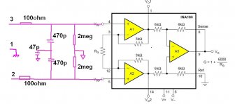
I think a INA163 instrumentation opamp is what you need, with an RF filter and some biasing resistors on the input. The gain can be adjusted from 1 to lots! The INA163 is available from Mouser and/or Digikey for about $9.
See attached (poor) drawing.
Paul Bysouth
I think a INA163 instrumentation opamp is what you need, with an RF filter and some biasing resistors on the input. The gain can be adjusted from 1 to lots! The INA163 is available from Mouser and/or Digikey for about $9.
See attached (poor) drawing.
Paul Bysouth
Attachments
OK. You just won't be getting full potential with the inbuilt resistors being there.
All op-amps need a DC path to ground to meet their input bias current needs. When you plug a guitar in it's fine because the pickup is connected to ground, but once you connect something with a balanced output - which will have DC blocking caps - the circuit will go wild. It will also go wild without any input connected.
Figure 13 is what I would recommend you try as it offers a lot of the features you need.
Paul, I like the idea of the INA163, and thank you for the sketch (your drawing is far better than mine btw 🙂 ) Your proposal looks like a similar but neater and more compact version of the circuit I had stumbled towards but also with the additional information on filtering and biasing, this is an enormous help! Thank you again, can't wait to try it!.
Richie, that makes sense in terms of the bias, and I think Paul's proposal has this drawn in.
Guys I am so grateful for your input!!
Richie, that makes sense in terms of the bias, and I think Paul's proposal has this drawn in.
Guys I am so grateful for your input!!
There is also the INA103 which is available in a DIP16 package, but at almost twice the price of the INA163. Digikey have them in stock at the moment.
Paul Bysouth
Paul Bysouth
I ordered an ina217 Paul, it was a toss up between that and the ina103 so fingers crossed. I also ordered samples from That Corp of their equivalent.
well after getting together with my friend this weekend, the first test of Paul's circuit (but using an ina217) were very successful. The balanced line out from my buddies multi-effects unit sounded perfect into the receiver 🙂 and then when I unplugged the multi effects and went straight into the circuit with the guitar, again it sounds bang on the money 🙂
Thank you so much for your help everyone.
If I can ask one additional question. I am getting a little confused by hi-z and low-z inputs. my audio interface has a switch that allows me to select hi-z or low-z. In Pauls cct, would the input impedance be set by the 2m resistors on the hot and cold inputs? This works nicely with the guitar (a nice high input impedance so the pickups don't get loaded) but why would I want anything with a different input impedance? why would this not work as well with a low-z input device? am I wrong to think that a big input impedance is always a good thing?
This works nicely with the guitar (a nice high input impedance so the pickups don't get loaded) but why would I want anything with a different input impedance? why would this not work as well with a low-z input device? am I wrong to think that a big input impedance is always a good thing?
Impedance is VERY poorly understood - what you DON'T want (except for a small number of exceptions) is impedance matching.
You want a low output impedance feeding a high input impedance, and this gives maximum voltage transfer without damping or loading of the source.
Generally you want the input impedance to be 5 to 10 times the source impedance, as otherwise you're adding the problems of a very input impedance for no advantage.
Thanks Nigel, the device I am building will have a couple of input, the guitar obviously but also balanced inputs from a multi effects unit. so it sounds like I should stick to the two meg resistors even for the inputs that will only ever be hooked up to the low z devices. I wonder why my audio interface bothers to have a hi-z /low-z selector?
Bigtim, that's a very good question you ask. In most cases a big input impedance is good, but it can make things a little noisier and more susceptible to RF pickup. So there is a trade off in some cases.
Thanks Richie, that makes sense and explains why it would be useful to have a selectable input impedance based on what is being plugged in.
In Paul's example circuit of earlier, do you think I am correct in assuming he input impedance will be 2m ohms? (I suppose I could always measure it 🙂 )
In Paul's example circuit of earlier, do you think I am correct in assuming he input impedance will be 2m ohms? (I suppose I could always measure it 🙂 )
I wonder why my audio interface bothers to have a hi-z /low-z selector?
Because it gives you improved noise levels, and particularly if you unplug the input.
It is likely that the 1M resistors are to signal ground.
If so, then they are in parallel to the actual Rin values.
The Rin values are more likely to be 2k to 100k depending on the designer's intentions.
The Hi Z for a direct feed from a guitar would be around the 1M range but that will be inside the guitar or on a very short cable from guitar to Hi Z input.
The balanced input is intended for longer cables and very low Z source impedances.
The guitar is NOT a low Z source impedance.
- Status
- Not open for further replies.
- Home
- Live Sound
- Instruments and Amps
- Balanced/unbalanced line receiver