Why would it need to have lower Rout ?
I believe it would be less sensitive to cable capacitance, for example.
When there is 500 pF capacitance parallel with 50 k load, the -1 dB point is at 30 kHz and with 700 pF the - 1 dB point is at 20 kHz respectively.
If this do not satisfy, a cathode follower can be added.
If this do not satisfy, a cathode follower can be added.
Hey boys, don't fight! 😀
I'm no expert, but I've built a circuit like artosalo proposed, except I used a 5687 (very easy to find, inexpensive, great tube). It does sound really fine. It's not hard to get working correctly, either. Snaps right into place.
I used an LM317 in the "tail" instead of the DN2540, because the LM317 requires only a single resistor to set the current using its built-in 1.25V reference, and it works every time. I know the DN2540 performs better in the upper frequencies, but I went for the convenience of knowing exactly what current I'd get with a particular resistor value (for Vref = 1.25V, Vref/R = I in amps).
artosalo, is there enough voltage between the 6N6P cathodes and ground to keep the DN2540 from switching off? Do you have like +5V at the 6N6P cathodes? Is that enough for the DN2540?
--
Last edited:
I used an LM317 in the "tail" instead of the DN2540, because the LM317 requires only a single resistor to set the current using its built-in 1.25V reference, and it works every time. I know the DN2540 performs better in the upper frequencies, but I went for the convenience of knowing exactly what current I'd get with a particular resistor value (for Vref = 1.25V, Vref/R = I in amps).
--
You can use a constant current diode instead of the LM317. They are also called current regulating diodes:
Mouser Electronics - Electronic Component Distributor Current Regulator Diodes
They are just 2 terminal devices, just like a normal diode, except that there's an FET inside, arranged as a constant current source.
Mouser Electronics - Electronic Component Distributor Current Regulator Diodes
I used to use those a lot, but I found they were too expensive, and didn't come in high enough current ratings. But I see that's all changed. Thanks!
The DN2540 and 10M25S depletion mode MOSFETs are the preferred choices these days (SY here turned a lot of people on to those). The LM317 is a poorer performing choice, but it's cheap, ubiquitous, and really easy to work with. And since the OP wants a simple project, I thought I'd throw that in.
But the CRD's you pointed out are even easier. You want 30mA? Put two in parallel and there you are. And they're less than $3 each now.
I wonder how they perform... Anyone?
--
is there enough voltage between the 6N6P cathodes and ground to keep the DN2540 from switching off?
There is about 58 Vdc at the cathodes and some 53 Vdc at the top of CCS.
Ofcourse the cathode voltage can be adjusted to lower level and then the
LM317 would work fine too.
The cathodes are at +58V? I can see why you need the input blocking caps.
For some reason that wasn't obvious from the schematic. How much current do you have the 6N6P triodes drawing? About 10mA each?
The 220R resistor sets the 'bias'? Ah, I see. The grid leak resistors define a floating ground, and the bias resistor goes there too.
--
For some reason that wasn't obvious from the schematic. How much current do you have the 6N6P triodes drawing? About 10mA each?
The 220R resistor sets the 'bias'? Ah, I see. The grid leak resistors define a floating ground, and the bias resistor goes there too.
--
Last edited:
Mouser Electronics - Electronic Component Distributor Current Regulator Diodes
I used to use those a lot, but I found they were too expensive, and didn't come in high enough current ratings. But I see that's all changed. Thanks!
The DN2540 and 10M25S depletion mode MOSFETs are the preferred choices these days (SY here turned a lot of people on to those). The LM317 is a poorer performing choice, but it's cheap, ubiquitous, and really easy to work with. And since the OP wants a simple project, I thought I'd throw that in.
But the CRD's you pointed out are even easier. You want 30mA? Put two in parallel and there you are. And they're less than $3 each now.
I wonder how they perform... Anyone?
--
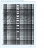
Performance depends on the current rating, with lower current values maintaining constant current over a wider voltage range than the higher current values. I am not sure about the conditions used for this test shown in the charts though. Also I think it's important to understand that when used in the tail of a long tailed pair, the voltage doesn't change a lot anyway. Here's a page about them:
http://www.centralsemi.com/product/cld/index.aspx
These curves look a lot better:
http://www.centralsemi.com/PDFs/products/ALL_SMD_CLD_curves.pdf
Attachments
Last edited:
How much current do you have the 6N6P triodes drawing? About 10mA each?
Total current for two triode halves is 23 mA.
Looks like about 5 to 15 volts is the sweet spot. I'd want to use them with a 6SN7, 6N6P or 5687 most of the time, so I'd need to choose an operating point with a bias of about -7V to -10V, if possible. Limits their usefulness, but otherwise they would be so easy to use. Thanks again.
Total current for two triode halves is 23 mA.
That's a good spot. I've used them there and they work well. I like that tube, too. It's a smooth sounding one.
--
Looks like about 5 to 15 volts is the sweet spot. I'd want to use them with a 6SN7, 6N6P or 5687 most of the time, so I'd need to choose an operating point with a bias of about -7V to -10V, if possible. Limits their usefulness, but otherwise they would be so easy to use. Thanks again.
Yeah, what's confusing to me is that other manufacturers, including Central Semiconductor, show almost a ruler flat curve for their CLD's (CRD's) over the entire voltage range, and Semitec does not. Vishay stopped making them apparently, but someone else is making their TO-92 style device.
For the two load resistors of the long tailed pair, I'd use a current mirror instead. There are current mirrors made as one device with 4 legs, so it's easy to implement.
For the two load resistors of the long tailed pair, I'd use a current mirror instead. There are current mirrors made as one device with 4 legs, so it's easy to implement.
This is only if you want one output from the differential pair.
- Status
- Not open for further replies.
- Home
- Amplifiers
- Tubes / Valves
- Balanced tube preamp schematic or kit?