Have you tried what was suggested in post15? You do not need the audio signal ground connected to the chassis. Pin1 to chassis on XLR input and output and no connection from attenuator to chassis unlike what you show in you drawing.
nash
nash
YES yes and yes.my 2 cents. A balanced input is supposed to work on the difference between the two input signals and should not be connected to ground. Whatever common mode interference exists on the ground connection is now part of your intended signals. See Bruno Putzey's article regarding the "G" word, which is his attempt at trying to denote that ground is not an absolute. You will need to implement a balanced attenuator that does not rely on a connection to ground.
The attenuator ( post #4 schemaic ) using XLR pin 1 is non sense.
XLR pin 1 is not an "audio signal ground".
Take a cutter and cut that connexion at the pots to "ground". Here is a balanced attenuator.
Let the pots float --> Noise gone.
In case the pots have a metal case, connect these cases to chassis XLR pin 1.
Last edited:
balanced attenuator using two DACTs
Here's an illustration of what I was suggesting in post #15. Two single ended DACT attenuators connected to form a balanced attenuator. It does assume that the DACTs are pretty closely matched and set to the same setting as you would have with a dual version. I assume a quad if you're dealing with stereo.
Here's an illustration of what I was suggesting in post #15. Two single ended DACT attenuators connected to form a balanced attenuator. It does assume that the DACTs are pretty closely matched and set to the same setting as you would have with a dual version. I assume a quad if you're dealing with stereo.
Attachments
I have a couple of Jensen Isomaxes so I could easily do it
Oh, man, dropout or sell somebody those hundredbucks boxes.
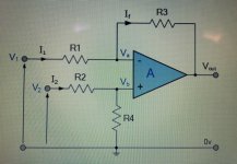
Put stupid differential receiver straight at the XLR-input of your enclosure. R1-R4 = 2k.

Set your Hypex’s as inverting amplifier, put 2k resistance at it’s inputs, put 10k linear pots inbetween input receiver and amps.

You’re in. Pretty nice CMRR and not less than ~100 dB clearly logarithmic regulation depth.
However, I set myself a goal of building a truly balanced differential amp with a passive volume control built-in and that's the fun I am after. Another amp module on the table is fully bridged, so the differential signal will go down all the way to subs' drivers.
First of let’s clarify things properly.
There are no truly balanced differential amps.
You have a choice inbetween:
1. 2-channel bridged amplifier, referenced to ground.
2. Fully-differential floating input amplifier
This is two very different classes having very different properties.
Last edited:
My noise problem is solved. It was a fairly trivial oversight in assembly. I follow AES 48-2005 (s2015) standard on grounding/EMC. My balanced stuff always has mains safety earth (equipment ground) , pin 1 to chassis, shielded internal cabling. This time something went wrong and I got noise from the DACT balanced attenuator. I checked again and found one end of the signal cable shield unconnected. Pin 1 from the input XLR is always grounded to chassis (and chassis to mains earth). Pin 2 ("+") is hot / non-inverting, Pin 3 ("-") cold / inverting. On the inside the cable ( I use mic cable) takes the signals with two internal wires and the shield must be connected to ground too. The Neutrik XLR socket has a special ground connector for the internal shield. I cut the isolation to exchange cables for the Canare star quad experiment and...the shield was not connected. On both channels. I connected them and voila! No noise. Perfect sound.
Connections are as per the DACT drawing I attached earlier. Some of you criticized the drawing ground lines. But it works. When I have some time I'll take one deck apart and check how it is built internally. Perhaps the ground does not connect with the signal line at all? Anyway, the proof is in the pudding. Now I am moving to my next project: BTL stereo amp with an autoformer volume control (balanced 4-gang). I already checked with oscilloscope on the bench that it gives nice phase/antiphase signals on the speaker outputs. Can I call this amp balanced differential, balanced or just differential?
Thanks everybody for your input, this always moves things forward. Special thanks to PRR who
inspired me to check the cabling which resulted in the disconnected shield discovery.
I'm glad you got it working. I still maintain that it would be more quiet if the attenuators were not connected to common. The DACT website shows them as a simple series connected set of resistors and the wafer switch connecting to the intermediate taps in the chain. In a perfect world the low side of the attenuators connected together would see no variation in signal if the two input signals are of equal amplitude and opposite phase. So connection to a quiet ground would be of no consequence. As soon as you connect to something other than quiet ground, such as the shield of the balanced input, you will affect the balanced signals coming in.
But the shield of the balanced input is grounded to the chassis also before the attenuator. That was the whole issue, that I missed that step. Is the chassis’ mains earth ground perfectly quiet? Of course not. There is no such thing as a perfectly quiet ground.
First of let’s clarify things properly.
There are no truly balanced differential amps.
You have a choice inbetween:
1. 2-channel bridged amplifier, referenced to ground.
2. Fully-differential floating input amplifier
This is two very different classes having very different properties.
What would you call a quad-mono amplifier where each channel serves one signal
of balanced differential lines (Left hot/cold, Right hot/cold)?
What would you call a quad-mono amplifier where each channel serves one signal
of balanced differential lines (Left hot/cold, Right hot/cold)?
Bridged.
But...
Your, at first sight independent channels, must be referenced to one reference voltage, in bridged configuration this is usually amplifier’s ground.
While your source signal are referenced to other reference voltage - source ground.
So, question, how would that grounds potentials be equalled?
How to best wire up a balanced attenuator is an interesting subject. I think it was either Bruno Putzeys or Bill Whitlock who pointed out that connecting the midpoint to ground actually tends to yield best performance, as counterinituitive as it may seem. This configuration will attenuate both differential mode and common mode signals equally. By contrast, common mode will pass through the floating midpoint configuration essentially unimpeded - so the more attenuation you need, the more disadvantageous the common mode to differential mode ratio becomes.
This is in contrast to the feedback network of a following instrumentation amp type receiver, which is in fact best left floating, as that keeps common mode gain at unity no matter how large differential mode gain may be.
This is in contrast to the feedback network of a following instrumentation amp type receiver, which is in fact best left floating, as that keeps common mode gain at unity no matter how large differential mode gain may be.
Bridged.
But...
Your, at first sight independent channels, must be referenced to one reference voltage, in bridged configuration this is usually amplifier’s ground.
While your source signal are referenced to other reference voltage - source ground.
So, question, how would that grounds potentials be equalled?
I had for a long time a pair of Spectron Musician III, amazing amps by John Ulrick. Each could work as stereo or "balanced monoblock". See the underlined passage at the bottom.
Spectron Digital Audio Amplifiers
Part III: How to use your Stereo Musician III in Balanced Monoblock Mode
1. Connect the right channel output of the Pre-amp to both inputs of the right channel amplifier. Do the same for the left channel amplifier i.e. connect Pre-amp left channel output to both inputs of left channel amplifier. If the preamp has two output jacks in parallel, run two cables, either RCA or XLR. If the preamp only has one output, a cable with a “Y” connection at the amplifier's end will be required.
We can customize this step for your individual needs - however, prior to the amplifier assembly only.
The most important major advantage of fully balanced mode in Spectron amplifiers is that transmission of both positive and negative signals (in each amplifier) is maintained separately from the amplifier's input to the speakers binding posts. Assuming that the signal path electronics are absolutely matched, all of the intrinsic amplifier distortions arrive at the speakers with practically identical amplitude but with opposed polarity and thus cancel each other. The result is a largely reduced noise and distortion-free sound transmission, leading to the spectacular improvement in three-dimensionality, finesse and resolution of detail in the music. Please note that advantages of fully balanced amplifations described above are not uniquie to Spectron! All amplifiers in the world can be used in the identical fashion, provided that their part tolerance is very, very high; otherwise your level of distortions will only increase!
And here's the story how John Ulrick with friends invented the use of switching amplifiers for audio
John Ulrick | Stereophile.com
Last edited:
This is misleading.Spectron Musician III, amazing amps by John Ulrick.
Assuming that the signal path electronics are absolutely matched, all of the intrinsic amplifier distortions arrive at the speakers with practically identical amplitude but with opposed polarity and thus cancel each other. The result is a largely reduced noise and distortion-free sound transmission

Actually, the cancelling only happens on the even harmonics.
You are left with the odd harmonics. This is what is the distortion you end up with.
Assuming that the signal path electronics are absolutely matched, all of the intrinsic amplifier distortions arrive at the speakers with practically identical amplitude but with opposed polarity and thus cancel each other.
Just translate 0,1% resistors in dB’s and you can realize by your own eyes, that’s all of this bla-bla-bla is a clear lie.
Bridged connection doubles OPS load (halves resistance), demands doubling of the output current and oftenly is a real reason of damaging of the amplifier.
Real bridged amps have half of the nonbridgeable amps supply rails, this results in a more or less tight matching to SOA of the OPS devices.
I forgot to mention that the bit about the noise -largely reduced- is BS too.Spectron Musician III, amazing amps by John Ulrick.
Assuming that the signal path electronics are absolutely matched, all of the intrinsic amplifier distortions arrive at the speakers with practically identical amplitude but with opposed polarity and thus cancel each other. The result is a largely reduced noise and distortion-free sound transmission
Wonders about distortion, wonders about noise.
As far as "Snake oil" is concerned, here we have a winner.

Putting marketing speak aside, can this amplifier be named “balanced differential” or is it only “differential”?
The 'correct' way of attenuating the input signal to a balanced amplifier is to use a single deck attenuator across the two inputs, and connect the wiper to the cold end. Actually a series attenuator (not stepped) is best for the application, with a series resistor on each input, sized to provide good attenuation steps.
You do need an additional buffer if you need to match gain and impedance of each stage correctly, but this attenuation method is actually the most optimal (IMHO).
You do need an additional buffer if you need to match gain and impedance of each stage correctly, but this attenuation method is actually the most optimal (IMHO).
- Status
- Not open for further replies.
- Home
- Source & Line
- Analog Line Level
- balanced stepped attenuator wiring

