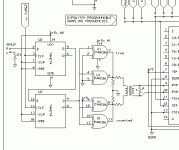
This time the attachment looks more sensible doesn't it? 
PLL=Phase-locked loop?
You mean I will use a PLL to reclock the I2S signal lines??

Jocko Homo said:On the RX side, you add a secondary PLL. Some guy who sometimes posts here sells one. (I know from personal experience that it works. Drawback: cost.)
PLL=Phase-locked loop?
You mean I will use a PLL to reclock the I2S signal lines??
Attachments
NO!
You are going backwards, bub........
You need 5V to drive those flip-flops.........isn't going to happen with 0.5 V p-p.
Your schematic looks like an output stage, only backwards. It doesn't work that way.
Yes, once you figure out the input, and save up $$$$$, you would stick a secondary PLL on the output of the RX chip. As far away s you are........forget it for now. Just too much stuff to confuse you.
Go look at the cheap SPDIF inputs. They work, the outputs don't.
Jocko
Let me give it a shot,...
Cathode leak,
I have been reading this thread from the start with a lot of interest, however due to misunderstandings it is on the wrong track and getting humorous.
Your question is about balance SPDIF.
SPDIF is used between a transport, the TX-side, and a DAC the RX-side.
Jocko's advice is:
The sbalanced SPDIF signal at the TX-side requires XOR-ing. The normal, and XORED-signal are together with GND send to the DAC (That is a balanced connection). You can use pulse-trafo's for isolation and adjusting the 5V to that of the AES/EBU standard
At tha DAC side the balanced signal can be input (via pulse trafo) into the ASRC (a CS8412, 8414), The ASRC used a PLL to split clock and data signals, however the PLL of the poular ASRC (8412, 14) are not good enough for sereous audio purposes, and therefore, Jocko's advice is:
The pulse-trafó's at the TX and RX side help in reducing problems due to impedance mismatches, which are the cause of reflections and thus sound degradation.
I Hope this clears up some mis understandings.
I have a question for the SPDIF-experts and that is:
when you decide to use a 2nd PLL, how much effort do you still have to put in the first PLL (in other words): how good must the signal be that is input in the second PLL, to let it pay of the extra costs).
Henk
Cathode leak,
I have been reading this thread from the start with a lot of interest, however due to misunderstandings it is on the wrong track and getting humorous.
Your question is about balance SPDIF.
SPDIF is used between a transport, the TX-side, and a DAC the RX-side.
Jocko's advice is:
Put the reclocker on the TX side, where you already have (or should have), a good, clean clock.
The sbalanced SPDIF signal at the TX-side requires XOR-ing. The normal, and XORED-signal are together with GND send to the DAC (That is a balanced connection). You can use pulse-trafo's for isolation and adjusting the 5V to that of the AES/EBU standard
At tha DAC side the balanced signal can be input (via pulse trafo) into the ASRC (a CS8412, 8414), The ASRC used a PLL to split clock and data signals, however the PLL of the poular ASRC (8412, 14) are not good enough for sereous audio purposes, and therefore, Jocko's advice is:
On the RX side, you add a secondary PLL. Some guy who sometimes posts here sells one. (I know from personal experience that it works. Drawback: cost.)
The pulse-trafó's at the TX and RX side help in reducing problems due to impedance mismatches, which are the cause of reflections and thus sound degradation.
I Hope this clears up some mis understandings.
I have a question for the SPDIF-experts and that is:
when you decide to use a 2nd PLL, how much effort do you still have to put in the first PLL (in other words): how good must the signal be that is input in the second PLL, to let it pay of the extra costs).
Henk
Jocko,
Just an observation.. It looks like the AD8561 comparator ("ultrafast", 7ns propagation delay) could be utilized to produce CMOS logic signal from SPDIF.. According to Elso Kwak it needs only a few mV above zero to give a high output state..
'cause I would have to step up the signal to 5Vp-p in order to utilize CMOS logic like 74 or 86 if I understand you correctly?
And I will have to step down signal to SPDIF standard (0.5Vp-p) before feeding the pulse tranny...? Resistors is the only way I can think of doing this...
Thanks for your feedback, Henk.
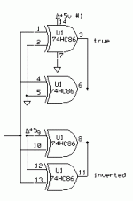
Can you tell me wether the '86 attached is correctly setup for this purpose?
Adjusting the CMOS 5V to the CS8412 inpust using the pulse-tranny will require adding a resistor network, right?
Calimero said:The sbalanced SPDIF signal at the TX-side requires XOR-ing. The normal, and XORED-signal are together with GND send to the DAC (That is a balanced connection).
Can you tell me wether the '86 attached is correctly setup for this purpose?
Calimero said:You can use pulse-trafo's for isolation and adjusting the 5V to that of the AES/EBU standard
Adjusting the CMOS 5V to the CS8412 inpust using the pulse-tranny will require adding a resistor network, right?
Attachments
No........
Transformers do not reduce jitter due to reflections. In most cases, they increase reflections. There is that little matter of leakage inductance to take into account.
Leave the comedy to the experts.
I do not like comparators, Elso does. Elso claims that it needs diodes to keep from frying the inputs. Adding diodes increases reflections.
You can get balanced with just with a transformer. Isolate the '841x from the transformer. Think buffer/inverter.
Jocko
Re: No........
With gain in the buffer then, to get CMOS voltage for the inverter?
Jocko Homo said:You can get balanced with just with a transformer. Isolate the '841x from the transformer. Think buffer/inverter.
With gain in the buffer then, to get CMOS voltage for the inverter?
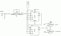
Why 2 flip-flops????
On the RX side................if you use an unbuffered one, it can do both functions.
Jocko
On the RX side................if you use an unbuffered one, it can do both functions.
Jocko
Jocko Homo said:Why 2 flip-flops????
That is a d**n good question. I'm not yet on wavelength with the basics of flipflops.. I've seen them wired like that in I2S reclock circuits so I figured it was the way to go.. It should be a single flop then, like attached?
Jocko Homo said:On the RX side................if you use an unbuffered one, it can do both functions.
A unbuffered 74? That would mean... 74HCU74? both functions? reclocking and... ...... ?
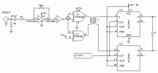
In the attached schematic I added the transformer to the 86 outputs directly, and an resistor across secondary windings.. Am I on the right track?
Attachments
Thanx for your helpfulness, Jocko, but I'll leave clocking out of the TX side and run balanced without reclocking, but i'll figure out somethin' for reclocking of the I2S lines on the RX side.. I'll start a new DAC thread shortly, but no TX reclocking for me yet... Maybe in the future though.. But thanx again for keeping up with my stupid nonsense.. I need to learn more about this stuff before I attempt to put this thread into a working shematic 🙁
Re: No........
I feel sad the SPDIF is so badly understood even by maufacturers. I am not going to point again at that chapter of Horowitz explaining the tranmission line as it should be....
No doubt you have built the best Interface. Too bad I can't have it......But put me on your list.
Oh yes, comparators like I use blow up with more than 3V on the input. SPDIF is a 0.5 V p-p so the signal will do no harm. Must be static........
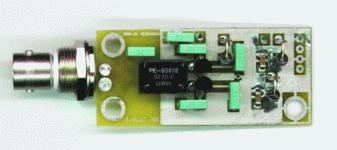
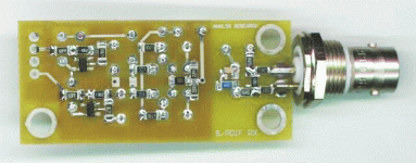
Attached a picture of my most wanted item!😎
Hi Jocko,Jocko Homo said:Transformers do not reduce jitter due to reflections. In most cases, they increase reflections. There is that little matter of leakage inductance to take into account.
Leave the comedy to the experts.
I do not like comparators, Elso does. Elso claims that it needs diodes to keep from frying the inputs. Adding diodes increases reflections.
You can get balanced with just with a transformer. Isolate the '841x from the transformer. Think buffer/inverter.
Jocko
I feel sad the SPDIF is so badly understood even by maufacturers. I am not going to point again at that chapter of Horowitz explaining the tranmission line as it should be....
No doubt you have built the best Interface. Too bad I can't have it......But put me on your list.
Oh yes, comparators like I use blow up with more than 3V on the input. SPDIF is a 0.5 V p-p so the signal will do no harm. Must be static........
Attached a picture of my most wanted item!😎
Attachments
cathode_leak said:
In the attached schematic I added the transformer to the 86 outputs directly, and an resistor across secondary windings.. Am I on the right track?
At the output of the flipflop you have your balanced outputs so the XOR gates are not needed. But the transformer does the balancing anyway so you could drive the trafo with ground on one pin. The only difference from balanced drive of the transformer is that you have half the signal level on the output.
How many times do I have to say to get rid of the reclocker???????
And it still is backwards.
I don't want to have to 'splain it again.
No, Elso, you can not have one. Only 3 were made. I don't even have one.
One is in Norway already. Maybe someone should drive over to where ever and copy it.
Jocko
And it still is backwards.
I don't want to have to 'splain it again.
No, Elso, you can not have one. Only 3 were made. I don't even have one.
One is in Norway already. Maybe someone should drive over to where ever and copy it.
Jocko
Re: How many times do I have to say to get rid of the reclocker???????
How can I seduce you to make some more????
I am not the kind of guy copying someones intellectual property......
😕
Jocko,Jocko Homo said:And it still is backwards.
I don't want to have to 'splain it again.
No, Elso, you can not have one. Only 3 were made. I don't even have one.
One is in Norway already. Maybe someone should drive over to where ever and copy it.
Jocko
How can I seduce you to make some more????
I am not the kind of guy copying someones intellectual property......
😕
Ask The Rutles...........
"All You Need Is Cash".
Actually, I need it more than they do. Find a bunch of guys who want one.......start a thread on a forum that I read more often, and bribe me.
Jocko
"All You Need Is Cash".
Actually, I need it more than they do. Find a bunch of guys who want one.......start a thread on a forum that I read more often, and bribe me.
Jocko
Re: Ask The Rutles...........
Jocko, You did not say the magic word on this forum. Can you say groupbuy?

Jocko Homo said:"All You Need Is Cash".
Actually, I need it more than they do. Find a bunch of guys who want one.......start a thread on a forum that I read more often, and bribe me.
Jocko
Jocko, You did not say the magic word on this forum. Can you say groupbuy?

- Status
- Not open for further replies.
- Home
- Source & Line
- Digital Source
- Balanced SPDIF reciever?
