I am walking around the Internet and cannot find satisfactory answer on this.
To feed a push pull amplification can I feed balanced signal directly (not via phase splitting circuit)?
Theoretically the balanced signal must be directly usable and purer.
Am I wrong here?
Nowadays media players with balanced output are easy to get and affordable.
Thank you.
To feed a push pull amplification can I feed balanced signal directly (not via phase splitting circuit)?
Theoretically the balanced signal must be directly usable and purer.
Am I wrong here?
Nowadays media players with balanced output are easy to get and affordable.
Thank you.
Yes, but you may need a balanced voltage amplifier to boost the signal.o feed a push pull amplification can I feed balanced signal directly (not via phase splitting circuit)?
Usable yes. Purer - maybe not; you have to consider where in your circuit you are going to eliminate common-mode signals.Theoretically the balanced signal must be directly usable and purer.
@df56: modern hi resolution media player can generate 1.7Vrms I consider this as quiet high.
@sy: I have an AK DAP with balance output from the site (Astell&Kern) they explain what they mean with balanced signal. It looks like phase inverted signals, I will check it on the oscilloscope.
@sy: I have an AK DAP with balance output from the site (Astell&Kern) they explain what they mean with balanced signal. It looks like phase inverted signals, I will check it on the oscilloscope.
Quiet, yes. High, no; not really enough for driving an output stage.vincenti said:@df56: modern hi resolution media player can generate 1.7Vrms I consider this as quiet high.
@rongon: DAP stands for digital audio player. My ak100 ii has balanced output and can easily drive solid state power amps.
@jazbo8: I don't plan to drive power stage directly, only looking where the redundancy is. There are many circuits out there but not many for balance inputs. Even the first pop up if you googling, the baby huey looks not right to me.
@jazbo8: I don't plan to drive power stage directly, only looking where the redundancy is. There are many circuits out there but not many for balance inputs. Even the first pop up if you googling, the baby huey looks not right to me.
Thanks, this looks much better than those I googled.Here is an example that uses two separate signals paths, with balanced feedback from the loudspeaker:
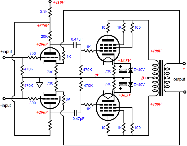
Alternatively you can allow the stages to share their cathode components, which improves CMRR, but then you can't apply feedback to the cathode.
The one from peter millet is also looks good.
There are also some schematics that really confuses me e.g.: Balanced feed, convert to unbalance, feed the signal to phase inverter than power stage. OMG.
Last edited:
On this picture there is an error because the loop of feedback has not a ground reference.
It can be done by two resistors of 100 ohm 2 w , one on + and other on - output terminal to ground..
If the output trafo has a center tap on secondary to ground it can be done as picture.
Just finished a full balanced amps with 4 x KT150 / channel, the input can be configured in non bal. by Sowter 3575 OCC
At 130 vrms output of driver I got 0,7 % Thd, 6922 input +6H30 driver is the circuit
On this picture there is an error because the loop of feedback has not a ground reference.
The feedback is differential. Note the cathode resistors in the first stage. This is a better scheme than relying on side to side balance of a CT transformer secondary.
The values are too high for the reference.
Since there's no significant CM current flowing there, I'm going to disagree strongly.
Is it possible adding ultra linear feed-back on the schematics mentioned above?
Just a thought.
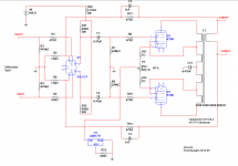
There are some mistakes on that schematic.
C21 is going from the center tap on the OPT primary straight to ground. Actually, that's where the B+ supply should be connected. Usually it would be about 450V there (might be different, that's just a guesstimate).
U1, the LM317H, is set to limit current draw to 2.5mA (0.0025 A). That pair of KT88's probably should be allowed to draw around 130mA (ballpark guesstimate). Also, without some kind of protection from overvoltage at turn on, an LM317H is likely to blow up if used that way. The voltage at the KT88 cathodes is likely to be about 45V, which is right up there at the upper limit of the allowable voltage through the LM317H. Maybe a TL783 would work better there (125V max volts). Or use a high wattage resistor there until you have everything working. Maybe 330 ohms, 15 watt wirewound. Experiment with current sinks and all that later.
On the KT88's, R9 and R10 should connect to pin 5 (the control grids). The screen taps from the OPT primary should connect to pin 4 on the KT88's (the screen grids).
I think you want to decouple R20 (2.31k) with a capacitor to ground.
R21 and R22 are 20k ohms, which are going to be much too heavy of a load on your 6SL7 tube. Those should be 100k or so. Then you might want to increase the value of R7 and R8 to 470k, if you can get away with it (ideally 10X the output impedance of V1).
V1 (the 6SL7) might not swing enough volts to drive both the KT88's and the global feedback loop to full output.
Anyway, I hope that helps.
--
- Status
- This old topic is closed. If you want to reopen this topic, contact a moderator using the "Report Post" button.
- Home
- Amplifiers
- Tubes / Valves
- Balanced Signal, Phase Splitter in Push Pull topology