Started a balanced power project. Wanted to share project progress here.
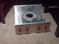
The case is Par-Metals 16"x16"x5"
-The balanced transformer is from Toroid Corp. of Maryland and its built to be used for balanced power. Its 60+/60-, with static shield, 2000VA, 17A.
-The primary line filter is a Schurter 20A.
Will be using a 15A slow-blo fuse or a 15A breaker.
-The outlets are Leviton isolated ground commercial grade 20A.
-The outlet covered are brass
Attachments

Last edited:
Added the following parts:
20A in-rush suppression NTC thermistor
X2 type .47uF 300v filter caps
15 amp thermal fuse (with reset)
Wattgate IEC plug and panel connector
20A switch. May add switch for primary and secondary windings.
20A in-rush suppression NTC thermistor
X2 type .47uF 300v filter caps
15 amp thermal fuse (with reset)
Wattgate IEC plug and panel connector
20A switch. May add switch for primary and secondary windings.
Last edited:
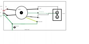
I have a schematic, but it may change. In any case, people might want to approach wiring differently, especially in the grounding scheme.
This schematic doesn't include filtering on the mains and secondaries.
Most importantly, this schematic doesn't include protection from in-rush current and fuses/breakers. All voltages inside this schematic are at lethal levels. Use caution, if attempting a build like this balanced power unit. I take no responsibility for injury or death resulting from thinking about attempting or attempting to build this project. You've been warned. Seek professional help in building this project, if you cannot. I'm not a professional.
Attachments
Last edited:
It doesn't have to be grounded, but it can be if you get better noise rejection.
However, the engineer at Toroid of Maryland said there is less noise using only the center tap. Version A of the schematic was presented to him and his response was to leave out the center tap to ground. I'm going to add a lift, just for the option of sending it to ground or not.
However, the engineer at Toroid of Maryland said there is less noise using only the center tap. Version A of the schematic was presented to him and his response was to leave out the center tap to ground. I'm going to add a lift, just for the option of sending it to ground or not.
I disagree. You should treat this as a separately derived system under the code. For safety, you should connect center tap to ground.
You should also use GFCI outlet(s).
If you have a dedicated line, or are going to install one, add a separate "technical" ground from the center tap in addition to the ground on the line side.
You should also use GFCI outlet(s).
If you have a dedicated line, or are going to install one, add a separate "technical" ground from the center tap in addition to the ground on the line side.
Last edited:
Like I said, people are going to want todo different schemes.
I'm going to go with the guy who designed it. 😉
I'm going to go with the guy who designed it. 😉
You can lead a horse to water...
Toroid didn't design balanced power. You're better off reading the Equitech site.
Toroid didn't design balanced power. You're better off reading the Equitech site.
I"m checking on this.
Maybe he assumed I was using regular outlets? I'm using isolated ground outlets. Maybe he thought it would create a loop?
I've seen where a center screw on standard outlets have been used as a ground.
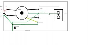
This was my schematic before I check with Toroid of Maryland's engineer.
Although I did delete the original, this is a modified version B.
Maybe he assumed I was using regular outlets? I'm using isolated ground outlets. Maybe he thought it would create a loop?
I've seen where a center screw on standard outlets have been used as a ground.
This was my schematic before I check with Toroid of Maryland's engineer.
Although I did delete the original, this is a modified version B.
Attachments
Last edited:
CODE (the one around here anyway) says that when you come off of a new winding the neutral must go to ground.
For noise you could ground it via an inductor, as long as the ground path at 60Hz can take out a fuse.
For noise you could ground it via an inductor, as long as the ground path at 60Hz can take out a fuse.
Here's is the response:
Dear Vince,
You have to decide it by yourself.
Since the balanced power transformer is an isolation transformer. In my opinion, there is no need to tie the center-tap to earth ground.
There is no electrical pass for the secondary to ground which can cause electrical shot.
Also, you need to consider the noise cancellation which is why you use the balanced power transformer in the first place.
So, you can tie or not tie the center-tap to earth ground. It is up to you.
To me, if not tie to ground gives me better noise cancellation, I will not tie the ground.
Regards,
Ming
At 02:27 PM 12/28/2012, you wrote:
Hi Ming,
One more question, if I may.
I was told that there must be a connection from center-tap to earth ground for safety.
Is this true? If it's not needed, how is safety guaranteed?
Thanks,
I built this exact same balanced design using a Signal Control DU-2. If you don't ground your ground lug at the outlets you will have all equipment many volts above ground potential and therefore a shock hazard. YOU have been warned!!!!!
Ming is an idiot or does not understand safety codes.
Ming is an idiot or does not understand safety codes.
Last edited:
That's fine dude. Just so you don't think I made up what I Wrote.
If you can't trust an expert, who can you trust?
And dont go around calling people idiots, ok. You don't know anything about the guy.
It makes you look bad. There could be the possibility you are wrong.
whats your level of understanding of isolation transformers?
If you can't trust an expert, who can you trust?
And dont go around calling people idiots, ok. You don't know anything about the guy.
It makes you look bad. There could be the possibility you are wrong.
whats your level of understanding of isolation transformers?
Two further notes on safety:
Firstly, the UK contingent should NOT do this, it has real and serious issues when done on a 240V system (There are ways of dealing with them but it gets complicated), see here for some discussion : Crosstalk: Readers' Writes
Secondly, you really do want to be treating this as a separately derived supply, with GFCI protection on the outlets as primary side protection will not sense a earth fault on the output side. Further the outlets should be protected by double pole breakers of capacity within the rating of the connected cables such that a short to earth from either leg will cause the breaker to open. You will also want to limit the length of the output cables to ensure the disconnect time requirement and I2t let through numbers are met in the event of an earth fault at the far end of a cable.
Not an easy thing to do right, dangerous if done wrong, and IMHO of dubious benefit if your audio gear is designed correctly.
Regards, Dan.
If you don't like tying the secondary ground to the earth ground directly you have an option of connecting them through a reversely paralelled high current rectifier diodes, a 35A rectifier bridge can be a perfect device here. This way you maitain the secondary isolated in normal conditions, yet the secondary ground will not go beyond the earth ground by more than a diode drop if a fault condition ever occurs.
vdi,
You should not take this as a personal attack. Our fellow members have raised valid points about safety in your chosen design, there are some pretty smart people one the forum.
Jam
You should not take this as a personal attack. Our fellow members have raised valid points about safety in your chosen design, there are some pretty smart people one the forum.
Jam
I built this exact same balanced design using a Signal Control DU-2. If you don't ground your ground lug at the outlets you will have all equipment many volts above ground potential and therefore a shock hazard. YOU have been warned!!!!!
Ming is an idiot or does not understand safety codes.
Exactly this.
Tying the centre-tap to the raw AC supply Earth does not compromise the functionality of the balanced supply, but it does:
1) stop failures in this transformer leaving any part of the outlet or connected equipment at deadly potential above your local 'earth' (e.g. your amp casework more than >50VAC above any other metalwork in the vincinity like your central heating radiators if applicable, or other mains-derived earth-referenced items etc)
2) Following the above, guard against the transformer failing at Pri:secondary isolation at sustained 4Kv withstand voltage (as would be required in europe for such a use). I bet that's not what you've paid for, god knows you wouldn't be asking such questions if so...
Basically if you do not tie any part of the secondary to the Mains supply system 'Earth/ground' you are demanding the transformer is qualified to 'Class Y1 / Y2' status.
Is it really..? Want to bet your family on it?
If you don't like tying the secondary ground to the earth ground directly you have an option of connecting them through a reversely paralleled high current rectifier diodes, a 35A rectifier bridge can be a perfect device here. This way you maintain the secondary isolated in normal conditions, yet the secondary ground will not go beyond the earth ground by more than a diode drop if a fault condition ever occurs.
That arraignment is for connecting the audio circuit to a grounded chassis. It's not for connecting the AC power Safety Ground/Protective Earth to the chassis.
@Jam
I'm not taking it personally. I don't like someone being called an idiot when they can't defend themselves.
Safe or not, bad advice or not, Ming said that its up to me to decide. Like I said before, I originally drew up the schematic with ct to ground.
I am so not taking this personally, that I will run ct to ground. I'm also going to add a GFCI receptacle. The GFCI I want costs $65, so I will use a standard 15 amp GFCI for now.
I knew I was going to get burned when I posted this project, because people over react. Someone always finds something wrong and just lets me have it, now to the point of being reluctant to post anything.
@Martin Clark
Thanks for the advice. Its a class B transformer. Just the same, I'll run ct to ground.
Toroidal Balanced Transformers
Transformer class rating
Attachments
Last edited:
- Status
- Not open for further replies.
- Home
- Amplifiers
- Power Supplies
- Balanced Power