@tonyEE To an extent you're probably correct. The issue I have is no option to run a fully balanced cartridge feed if it doesn't allow for easy separation of shield and the internal strap to neg on one channel (if so equipped). I have several MC carts that don't allow this.
The other issue is intermittent appliance noise depending on time of day and load. I ran a PS Audio AC regenerator and had constant issues with it going through output transistors from sloppy heat sinking internally. The best results obtained were with an isolation transformer and LPF, but the bad odd order harmonics still made there way though along with high HD components. Its fat easier to isolate the arm from the TT chassis than invest in more elaborate gadgets to bandaid what could otherwise be a simple hardware solution fix.
I'm not going to use Teflon for insulation, as it has problems with static fields wandering along the surface where it acts as dielectric. Creep is a whole different issue. Nylon doesn't do any of this stuff and is far easier to work with. Im using 2 layers of 1 mil Kapton polyimide to isolate the arm base flange to chassis flange. Its very tough stuff and versatile.
AC supply wise, I can implement a high Q bandpass filter to only allow 60 hz through the xformer.
1 mil Kapton polyimide should do just nicely. I really ought to keep some in stock. Yes, it's remarkably difficult to clean up the mains. And not helped when others nearby use something that should never have been available for sale because it doesn't meet EMC standards.
I already have an EMI/RFI filter network in the mains panel and the mains feed to the audio system has 2 dedicated 20A feeds with split neutral. The main issue is the airborne RFI from neighbors using high powered G/N band wifi routers. I did a spectrum analysis recently and counted over 10 high powered wifi networks in the nearby neighborhood. When my next door neighbors air compressor kicks on, it emits an RF burst that makes my phono setup give off sharp snaps. Nothing really loud, but very annoying. Not much you can do if the grid is so contaminated and others emit alot of RF noise. I'm tempted to screen the preamp and source gear in a separate enclosure using fine copper mesh.
A few years ago, I had to take a piece of equipment having an LSK170C front end where my detection level was six standard deviations above the noise through EMC susceptibility testing of 10V/m. I found (as has everyone else who has done this) that self-adhesive copper tape and clip-on ferrites are the answer. You'd be amazed how tiny a gap can cause trouble. In my case, it was a gap about 120mm long by 0.1mm wide. Copper tape over it solved susceptibility at 600MHz. The production fix was a 20mm x 20mm patch of copper tape inside. Self-adhesive copper tape is widely available as slug tape for gardeners and much cheaper than from electronics factors. Put it over every joint (mechanical joints in chassis, not electrical joints!). I now have clip-on ferrites at each end of all my cables whether mains cables, BNC-BNC, XLR-XLR; it's just not worth making a measurement mistake in the lab from dodgy cables.
The other place RF gets in is common-mode via the aerial of mains wiring. Topaz Ultra-Isolator transformers are nearly unobtainium now, but only nearly. Obviously, you need screened wiring afterwards.
The other place RF gets in is common-mode via the aerial of mains wiring. Topaz Ultra-Isolator transformers are nearly unobtainium now, but only nearly. Obviously, you need screened wiring afterwards.

How does that go along with the need of chassis heat ventilation? How does one think there? I mean, unwanted gaps shall ofc be closed but usually electronics need at least some ventilation.
Does it help to off center vent holes in layers?
Does it help to off center vent holes in layers?
You are correct; it makes cooling an issue. But once we've amplified signals to line level, we don't attenuate them again because it would compromise noise. So that means there's only one stage of high gain amplification. So we put that one stage in its own box. But low noise electronics has a nasty habit of forcing high currents in the input devices. So we thermally bond them directly to the casing. And anything else that gets warm (regulators). Thus, it is possible to use a case that doesn't need internal ventilation. Might need a heatsink on one or more sides, though. It requires thinking about EMC and thermal management early on.
I'm afraid I don't know enough about RF to say whether offsetting holes would stop RF getting in. But it would undoubtedly restrict ventilation. 😉 And you'd be amazed how small the hole area is of perforated sheet.
I'm afraid I don't know enough about RF to say whether offsetting holes would stop RF getting in. But it would undoubtedly restrict ventilation. 😉 And you'd be amazed how small the hole area is of perforated sheet.
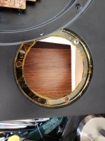
Here are the fruits of my labor. Its not easy to get an evenly thick application if you don't have a large flat surface. I applied 3 layers of 1/2 mil kapton tape and drilled out the locating holes to .280". This is to receive the insulated threaded standoffs from the arm base.
Attachments
Crossed fingers it works. Don't see why it shouldn't. It really doesn't need to be a good insulator - anything over 1k would lprobably be quite adequate. It would be interesting to do some calculations to refine that wild "out of the air" figure.
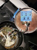
The arm is back in and well isolated. I measured in excess of 30 meg ohms with my HP meter's highest setting.
Silver for its lower electrical resistance and antibacterial properties.
Lol yeah, copper is antimicrobial too. Its the second best conductor next to silver. Its definitely cheaper too.
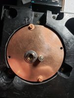
I ended up building a copper end cap to install a single 5 pin mini XLR connector and extra earth terminal. I chose a single connector because of the grounding scheme, so it didn't loop a second ground run back on a second XLR shield. The earth originates from the phono pre PS and runs down the cable length, TT and splits to returns to the input XLRs local earth. I used mogami shielded wire, as it only has 8 pF capacitance per ft.
Attachments
- Home
- Source & Line
- Analogue Source
- Balanced phono cartridge grounding