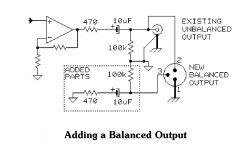
I'm wanting to add balanced outputs to some of my pre-amps. I've read the Jensen document and am planning to use the 'simple alternative', which I'm attaching for convenience. This just involves adding two resistors and a capacitor to balance the impedence.
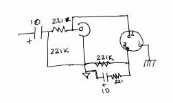
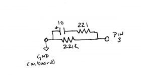
Since this question comes up often enough, I'm thinking it would be worth it to make up a simple PCB that would contain the required components. The other two attachments show how this would go in the context of the Pass B1 Korg and then just the parts that would be on the PCB. Of course the actual board would be designed so that any values could be used. Can someone verify that I've got this right before I fire up KiCad to build the board?
One slightly unrelated question about KiCad, in case anyone reading this happens to know: How do you add mounting holes?
Attachments
It is unfortunate the Bill Whitlock calls this circuit a 'balanced output' because it is actually a single ended output with equal impedance to ground on both + & - legs. The - leg stays at ground potential and does not swing in voltage that mirrors the + leg.
It should be called a simple unbalanced to balanced interface.
From the point of view of common mode noise rejection at the load it has some merit for applications where there is a long cable between source and load, or where for some reason the interconnecting cable cannot be screened. However to achieve high CMNR at the load very tight tolerance resistors need to be used, at the very least 1% resistors selected on test, or preferable 0.1% or better resistors.
Also note that an unbalanced output connected as shown may not function properly becasue it no longer has a signal ground on the shell of the connector and could introduce an unintended ground loop or ground noise.[/I]
Because the output of this 'balanced' adapter is still referenced to ground, it does not offer a solution to the 'pin 1 problem' which leaves open the possibility of ground loop induced noise between source and load, thus missing one of the main reasons for a true balanced connection between two pieces of audio equipment.
To quote from Rane's excellent Sound System Interconnection Technical Note (I have edited in square brackets to make it specific to this case):
Floating, Pseudo, and Quasi-Balancing
...[an] output called floating unbalanced, sometimes also called psuedo-balanced or quasi-balanced. In this configuration, the [ground] of the output stage is not connected inside the unit and the [pin 3] is connected (usually through a small resistor) to the audio signal ground. This allows [pin 2 and pin 3] to "appear" as an equal impedance, not-quite balanced output stage, even though the output circuitry is unbalanced.
[This] often works to drive either a balanced or unbalanced input, depending... When it hums, a special cable is required. See drawings #11 and #12, and do not make the cross-coupled modification of tying the [pin 3 and pin 1] together.
Sound System Interconnection
You don't need to make a PCB for a capacitor and a resistor. Solder them directly to the XLR or Jack. I have done this mod on a cheap mixing desk.it would be worth it to make up a simple PCB
It is unfortunate the Bill Whitlock calls this circuit a 'balanced output'
Call it cheated balanced output. It doesn't matter that one of the cables doesn't carry any signal. What matters is maintaining equal impedance on both wires. From that point of view it is indeed balanced. Many mixers from reputable manufacturers use this type of connection on the booth and sub-zone outputs.
it no longer has a signal ground on the shell of the connector
None of my XLR cables have the shell connected to the shield / ground and so far I haven't had problems.
If You really want to go the correct way, check the output op-amp type and add another in inverted configuration to drive the Cold pin. A dual op-amp could than drive both channels, and You will have higher output to drive PA amps for example.
Use at least 1% metal film precision resistors. The blue ones You know.
The quote is a reference to the RCA output connection, not the XLR one.Quote: it no longer has a signal ground on the shell of the connector
None of my XLR cables have the shell connected to the shield / ground and so far I haven't had problems.
One slightly unrelated question about KiCad, in case anyone reading this happens to know:
How do you add mounting holes?
Create a mounting hole - Layout - KiCad.info Forums
If you use Osh Park, three of those boards would cost around $3 including shipping.
I've seen about every opinion on this kind of circuit. I'm not qualified to have an opinion myself, so I'm planning to try it. I've also got a 'black box' I've built with two Jensen transformers that will do the same thing, so I'll be able to compare once it's done. But it'd be nice, in some cases, to have something internal to the preamp and not have to rely upon the external box.
I am puzzled by the remark about the RCA ground. That is still connected to signal ground, isn't it? That part doesn't change.
I will make a point of matching the resistors. I usually use Dale RN55s, which are 1% at worst. Fortunately, they're cheap enough I can buy a couple dozen and find ones that match well.
The PCB is just for convenience. I like to keep everything at neat as I can. I'll post the Gerber once I've got it.
I've seen about every opinion on this kind of circuit. I'm not qualified to have an opinion myself, so I'm planning to try it. I've also got a 'black box' I've built with two Jensen transformers that will do the same thing, so I'll be able to compare once it's done.
I am puzzled by the remark about the RCA ground. That is still connected to signal ground, isn't it? That part doesn't change.
There's opinion... and there's science. Science wins every time. I am not saying that the simple pseudo balance circuit will not work; in fact I gave a simple explanation of its benefit compared to an unbalanced connection and its disadvantages compared to a truely balanced output, plus references to more detailed explanations. It will pass signal between the two components and may provide a degree of common mode noise rejection if you have extremely long or very badly screened interconnects provided the interconnects are correctly constructed. Have a look at the Rane link I provided for cable constructions between different types of 'balanced' input and outputs. There is not one single ideal connection for all possibilities of type of output and type of input using balanced cables.
Oops, I made a mistake; an alarm went off when I saw the chassis connection to the RCA. If the RCA shell goes to chassis and signal ground, it will likely introduce another problem. The chassis and signal grounds are quite likely to be at different potentials and that connection can cause an earth loop noise issue. It's a different manifestation of what's called the "pin 1" problem in professional audio. I would make sure that the RCA sockets are an insulated type and not connected to chassis.
The interconnection test is to listen to the noise floor of your amplifier and speaker combination with nothing else connected, and the amplifier set to normal loud or maximum gain. This is the system's 'noise floor'. Nothing you connect upstream should degrade the noise floor.
... I will make a point of matching the resistors. .... 1% .....
How about the capacitor(s), if any?
The 10uFd shown is already 265 Ohms at 60Hz. So even perfectly balanced the impedance is up 56% at a popular trouble frequency. Then the "10uFd" is typically -20%/+50% (yes, this is changing, slowly) so 307 to 384 Ohms. And an affordable/compact 10uFd is an electrolytic and they tend to drift (both ways) over the months and years.
You could easily come out 777 one side 854 other side, at 60Hz, just due to capacitor tolerance, before drift. The 470 1% (465-476) resistance tolerance is nearly insignificant.
How about the capacitor(s), if any?
The capacitors form part of the output impedance along with the 470Ω resistors. The corner frequency is not set by the 470Ω, but by the combined 100kΩ in // with the input impedance of the next stage, say 22kΩ. Together that load would be ~18kΩ. The frequency at which the capacitor is 18kΩ is about 0.9Hz; at 50Hz, it is ~320Ω as you pointed out. Using this example of a 22kΩ load a ±10% variation of capacitor values will in the worst case degrade CMRR at 50Hz to around -48dB, ±20% to -43dB.
Edit: Sorry I live in a 50Hz world, hence my choice of frequency for the example.
Last edited:
There's opinion... and there's science.
Well, yes, but it turns out that people who (as far as I can tell) all know the science still disagree. That's normal.
Oops, I made a mistake; an alarm went off when I saw the chassis connection to the RCA. If the RCA shell goes to chassis and signal ground, it will likely introduce another problem.
I didn't notice that in the Jensen drawing. But I wouldn't connect it that way. Most of my cases I build from wood anyway, so there isn't a chassis ground. Signal ground gets connected to earth ground either through a low value ceramic capacitor or through one of these kits.
Thanks for the illuminating discussion. I can build these things. It doesn't mean I understand how they work. In any event, I will do my best to match the caps, too, though I understand that is no guarantee they will stay matched.
I will guess that the transformer-based solution will prove to be better, but there's only one way to find out...
I will guess that the transformer-based solution will prove to be better, but there's only one way to find out...
Well, yes, but it turns out that people who (as far as I can tell) all know the science still disagree. That's normal.
I am not saying you shouldn't implement a pseudo balanced output, just that you should understand what it is, what it does and what it does not do; after all you asked for advice.
Grounding in audio equipment interconnections has been so poorly understood and misapplied since forever, which is why the Audio Engineering Society has published standards for the proper interconnection of audio equipment.
People are human, and don't always apply science correctly. I'd even wager that many designers of consumer audio equipment aren't aware of the AES standards. That leads to circumstances where people make their own rules and the appearance and disappearance of noise in interconnected systems seems to follow no logic. It is no wonder people form their own opinions based on personal experience, which doesn't make them right or the underlying science wrong.
https://www.aes.org/standards/comments/drafts/aes48-xxxx-190121-cfc.pdf
I will guess that the transformer-based solution will prove to be better, but there's only one way to find out...
What you find out will only be applicable to the circumstances of your particular setup. It will not tell how the circuit behaves in different circumstances. See my previous post about why people develop misinformed opinions about sound system interconnections.
- Home
- Source & Line
- Analog Line Level
- Balanced Output PCB