Seeking some advice and opinions.
I've been designing amp attenuators on the Marshall forum, and there's been quite a few successful builds. These take a signal from the amp OT, send it trough a switched network of inductor and resistors, to go to the speaker. It works great but so far there's no line-out. Also, I'm not contecting to any chassis or ground so far.
The attenuator can be used as a load box too, and id like to put up a simple and versatile line out, to go to external cab sim, IR box or mixer. Some such units do this just with a pot and resistor to make an unbalanced output, others like Suhr use a transformer and give a balanced option to an XLR socket. Im thinking it should be possible to get balanced, without a transformer
What are your views? and what about grounding?
I was thinking about using a balanced resistor circuit to feed a reduced signal derived from each end of the OT, to the hot and cold pins of an XLR. The XLR ground could be referenced by equal resistors to half way from hot to cold, or maybe lifted?
What is "balanced" in your shop?
A lopsided feed from a typically grounded speaker winding is not-so-balanced in my opinion. It can work very well.
Where are you going that unbalanced won't work? Unbalanced source to balanced receiver is a workable technique.
A lopsided feed from a typically grounded speaker winding is not-so-balanced in my opinion. It can work very well.
Where are you going that unbalanced won't work? Unbalanced source to balanced receiver is a workable technique.
Thanks for relying. For my own use at home, I reckon I'd get by fine with a simple unbalanced line out, with a pot and series resistor to bring the level down. Maybe that's enough
But since others are building from my design I want to post a diagram that covers the most likely uses and is versatile plus is good practice. Maybe there's a couple of versions. So I'm interested in any opinions.
My attenuator is on this thread, currently at 78 pages, but the key info is in post 1, and the first diagram.
Simple Attenuators - Design And Testing | MarshallForum.com
This is something I've been thinking about, for a simple all passive balanced line out:
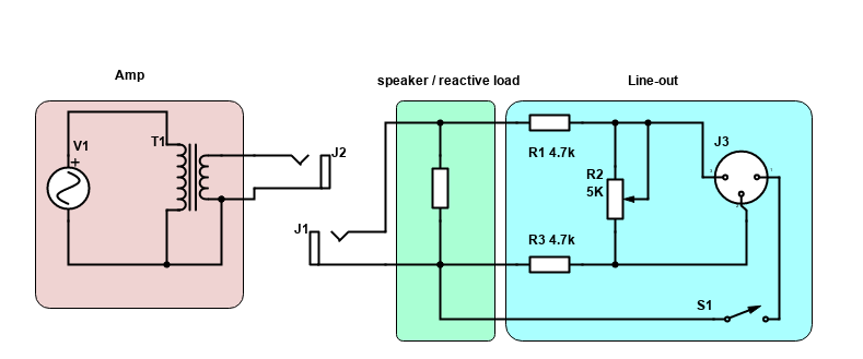
It represents a guitar amp, a reactive load in the green box, and the line out circuit
What do you think? As I understand it, the key thing with balanced, in order to reject noise in-line is to get the same impedance to ground on hot and cold. Here both see the 4.7k resistors, and whatever input impedance's there are at the mixer. It slightly unbalanced due to the load impedance seen by the hot side, but its quite small compared to the line-out resistors. R1 could be tweaked to partly compensate if needed
Could this work? is it a good idea or is it nuts?