Hi Guys,
Here's a simple mixer/summing amp which works quite well in mono at the moment..However I need to add a balanced output as well.What confuses me is the master volume pot which is actually feeding the o/p socket.
Q:Would the balanced o/p as I've drawn in the diagram work properly?
The o/p cap is 10uF electrolytic...is this unnecessarily high value?
Btw,the NE5532 will drive loads down to 500ohms which is adequate for my needs.
Thanks
Attachments
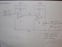
Well, it's not balanced! Pins 2 & 3 need to be symmetrical to signal ground at all frequencies and all volume levels.
And pin 1 needs to be connected to chassis ground not signal ground.
With a 500ohm load 10uF is not too big.
And pin 1 needs to be connected to chassis ground not signal ground.
With a 500ohm load 10uF is not too big.
Thank you indeed!
Yes,yes..I now realize what you meant by symmetrical signals!So what I need is a resistor divider to tap part of the signal from the single ended o/p?
Yes,yes..I now realize what you meant by symmetrical signals!So what I need is a resistor divider to tap part of the signal from the single ended o/p?
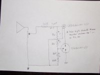
To get balanced outputs add a non inverting buffer stage to drive pin 3. It gets its signal from the output of the first stage.
I'd put the level control at the input - as shown the output impedance changes with it's setting. It also makes level control easier. If you put it between stages it will affect the gain of the inverting buffer.
I'd put the level control at the input - as shown the output impedance changes with it's setting. It also makes level control easier. If you put it between stages it will affect the gain of the inverting buffer.
Kevin,could you please tell me if this will work? I've drawn this from memory from a similar diagram I came across many moons ago!I'm not sure how high the divider Ra,Rb values should be.I suppose these should be very high in hundreds of K ohm if not in the M ohm range?
Attachments
Bob Ellis,
Thanks,yes I did come across such a design..but there's no room for an additional IC on my board!That's why I wanted something simple yet would give me a true balanced o/p. Dr.Linkwitz has given a simple diagram,but it doesn't look like a true balanced..(his article on mic preamp)
Yes you're spot on with regard to o/p impedance changing in the present configuration.This is what prompted me this post in the first place.
As for your suggestion of moving the pot to the i/p, I presume this pot would follow the 2 summing resistors? The 2 summing Rs are already preceded by 2x10k pots...so would this have any adverse effect?
Q:What would happen if I change the 10kR to a 10K pot in the feedback loop in the first stage & use this as a volume/gain cont? Would this have the same effect on gain or impedance?
The 2 summing R's to the mixer are already preceded by 2x10k pots from 2 separate signal outs.
Thanks Andrew - that's the reference I was trying to recall.
Teleman - you can use variable gain to control the volume. Whether the sound characteristics change with gain enough to be noticeable is for your ears to decide. Some say yes, some say not.
Teleman - you can use variable gain to control the volume. Whether the sound characteristics change with gain enough to be noticeable is for your ears to decide. Some say yes, some say not.
AndrewT,you're super efficient! I just found what I was looking for in the Jensen link,page 3, fig;2.4.It shows a very simple yet a true balanced out put with an addition of only 3 components! Just what I needed!
I will test it tonight & post you the results.I did try to read the whole article on "Balanced Technology" by Mr.Douglas Self,but didn't grasp it fully,so more reading over the weekend!
Bob Ellis,as for connecting a pot in the feedback loop..I just remembered my bad experience with the piezo preamp.Yes,it changed the tone circuit completely,especially on higher volumes...gave a very nasty "mid boost".So wouldn't go that path again,however,I will follow your previous suggestion of connecting a pot in the input & will give you the results in the morning.
Thanks Kevin for your invaluable tip on signal ground/earth.It really helped!
Thanks guys!
Looking at page 3,fig.2.4a http://www.jensen-transformers.an/an003/pdf in the unbalanced out put both the signal-common(0) & the (earth) ground wires are shorted.Is this correct or just an oversight?
Last edited:
Bill Whitlock of Jensen is one of few authorities on this type of circuit. So I think that is the correct planned connection. Both the input and output un-balanced jacks are connected to chassis ground. It's the same way in all the drawings.
Does this mean that both the unbalanced in/out common wires should be grounded to the chassis instead of the signal (0) ground? In that case won't any signal or a cable plugged in to these will see an open circuit,by virtue of the fact there won't be any direct connection between signal ground ie:0v & the chassis ground!
Then what would be the function of the signal ground?
Do you have any idea as to why it is wired this way? Would you mind elaborating this please 'cause I'm thoroughly confused now!
Then what would be the function of the signal ground?
Do you have any idea as to why it is wired this way? Would you mind elaborating this please 'cause I'm thoroughly confused now!
Last edited:
the triangle symbol is the signal ground.
The fork symbol is the chassis.
What's the confusion?
Rane note165 might help.
The fork symbol is the chassis.
What's the confusion?
Rane note165 might help.
The confusion is when both the triangles & forks are tied together as in fig.2.4 on page 9 in the http://www.jensen-transformers.com.an/an003.pdf !!
Does this mean that both the unbalanced in/out common wires should be grounded to the chassis instead of the signal (0) ground? In that case won't any signal or a cable plugged in to these will see an open circuit,by virtue of the fact there won't be any direct connection between signal ground ie:0v & the chassis ground!
It's not instead of the signal ground, it's in addition to the signal ground.
Ah,Yes of course & thank you for reminding me about the 2 wires + screen!......
Taking the cue from Kevin,I had another look at Douglas Self's pages,it suddenly dawned on me that I had completely forgotten about the 2 wires + the screen involved!
So sorry guys to have bothered you all unnecessarily!I do get wires crossed in my brain sometimes!Needs proper screening I suppose!!
Taking the cue from Kevin,I had another look at Douglas Self's pages,it suddenly dawned on me that I had completely forgotten about the 2 wires + the screen involved!
So sorry guys to have bothered you all unnecessarily!I do get wires crossed in my brain sometimes!Needs proper screening I suppose!!
Last edited:
- Status
- Not open for further replies.
- Home
- Source & Line
- Analog Line Level
- Balanced mixer output?