Hello,
A few days ago a good friend of mine asked me for help. He wanted to utilize his guitar effect pedals with vocal microphone at stage.
After short research I found that off the shelf solutions (like Radial Voco-Loco for example) aren't so affordable, so I came with idea doing it DIY way.
Basically I wanted balanced XLR microphone input, single ended 6.3mm send/return and balanced XLR line level output.
Design assumptions:
- Lowest noise and distortion possible
- Gain range suitable for both dynamic and condenser microphones
- Switchable +48V Phantom power supply
- Universal and easy to use
- Reliable
- Compact, fitting inside Hammond 1590BB enclosure
- Rather simple and elegant circuit as I don't like to make things over-complicated
- Not too expensive
Later, after hearing friend's suggestions:
- Possibility to bypass effects with foot-switch
- Dry/Wet (blend) mix
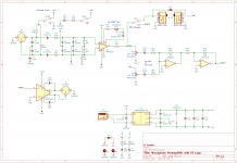
Considering the following I decided to use ICs from THAT Corp. - 1510 as mic pre and 1646 as balanced line driver. Both could be substituted with slightly worse INA217 & DRV135 from Texas Instruments.
Dry/Wet mixing circuit is rather simple, virtual ground type.
I could have used one dual pot instead of two singles but that way gives more flexibility.
If I'm not mistaken now it is possible to use it as two channel mixer - using mic input and return jack as second channel.
Two inverting op amp stages are used so absolute polarity is preserved.
Only thing I'm not completely sure is if should I leave it as is with buffered pot or place pot in place of feedback resistor, getting more gain possibilities.
OPA1678 input bias current is extremely low so coupling cap isn't probably required.
Power supply design was definitely the hardest part of design process. More on this can be found at my another thread - https://www.diyaudio.com/forums/pow...-getting-15v-15v-48v-single-power-supply.html
Phantom power and grounding are really tricky matters. I had to did a lot of research in terms of proper grounding and "Pin 1 problem".
Some really helpful papers:
Ian Thompson-Bell - Mixer Grounding 101
Rane note 151 - Grounding and Shielding Audio Devices
Rane note 165 - Pin 1 Revisited
After a lot of thinking and with help of fellow forum users I finally decided that I gonna use external +48V SMPS and integrated DC/DC converter to +/- 15V.
My last concern if its ok to "tie" enclosure and signal grounds with LED and resistor when SW1 turns phantom off. Or maybe DPDT switch should be used?
There is a jumper, so I have a bit of flexibility with grounding. Depending on the results of measurements, I can tie grounds or leave them unconnected.
Most sources recommends tieing them in one point. But isolated DC/DC converters are pretty new thing, maybe they didn't been considered? Having completely floating supply sounds indeed interesting.
Schematics are attached to post. Now fun part begins - PCB layout 😀
Regards,
Miłosz
A few days ago a good friend of mine asked me for help. He wanted to utilize his guitar effect pedals with vocal microphone at stage.
After short research I found that off the shelf solutions (like Radial Voco-Loco for example) aren't so affordable, so I came with idea doing it DIY way.
Basically I wanted balanced XLR microphone input, single ended 6.3mm send/return and balanced XLR line level output.
Design assumptions:
- Lowest noise and distortion possible
- Gain range suitable for both dynamic and condenser microphones
- Switchable +48V Phantom power supply
- Universal and easy to use
- Reliable
- Compact, fitting inside Hammond 1590BB enclosure
- Rather simple and elegant circuit as I don't like to make things over-complicated
- Not too expensive
Later, after hearing friend's suggestions:
- Possibility to bypass effects with foot-switch
- Dry/Wet (blend) mix
Considering the following I decided to use ICs from THAT Corp. - 1510 as mic pre and 1646 as balanced line driver. Both could be substituted with slightly worse INA217 & DRV135 from Texas Instruments.
Dry/Wet mixing circuit is rather simple, virtual ground type.
I could have used one dual pot instead of two singles but that way gives more flexibility.
If I'm not mistaken now it is possible to use it as two channel mixer - using mic input and return jack as second channel.
Two inverting op amp stages are used so absolute polarity is preserved.
Only thing I'm not completely sure is if should I leave it as is with buffered pot or place pot in place of feedback resistor, getting more gain possibilities.
OPA1678 input bias current is extremely low so coupling cap isn't probably required.
Power supply design was definitely the hardest part of design process. More on this can be found at my another thread - https://www.diyaudio.com/forums/pow...-getting-15v-15v-48v-single-power-supply.html
Phantom power and grounding are really tricky matters. I had to did a lot of research in terms of proper grounding and "Pin 1 problem".
Some really helpful papers:
Ian Thompson-Bell - Mixer Grounding 101
Rane note 151 - Grounding and Shielding Audio Devices
Rane note 165 - Pin 1 Revisited
After a lot of thinking and with help of fellow forum users I finally decided that I gonna use external +48V SMPS and integrated DC/DC converter to +/- 15V.
My last concern if its ok to "tie" enclosure and signal grounds with LED and resistor when SW1 turns phantom off. Or maybe DPDT switch should be used?
There is a jumper, so I have a bit of flexibility with grounding. Depending on the results of measurements, I can tie grounds or leave them unconnected.
Most sources recommends tieing them in one point. But isolated DC/DC converters are pretty new thing, maybe they didn't been considered? Having completely floating supply sounds indeed interesting.
Schematics are attached to post. Now fun part begins - PCB layout 😀
Regards,
Miłosz
Attachments

Hi, this is a nice variant, with the effects loop and dry/wet mixer.
Here are some quick tips, some of which I learned while making my mic preamp (shameless plug)
1. Read the "Phantom Menace" papers. The 1N4148 diodes for protection will not hold up.
2. You might want AC-coupling before the potmeter to avoid scratching noise due to DC.
3. The gain of the final inverting stage will vary depending on potmeter setting due to the output impedance of the potmeter varying from 0 to 2k5 depending on angle. But that might be what you want?
4. If you used non-inverting buffers for the final stage, you could save one dual-opamp I think.
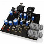
After considering your suggestions final version probably gonna look like this.
Hammond 1590BB is a few millimetres too short to accommodate horizontal XLR connectors so I need to find other case.
1590C is too chunky for stompbox. Vertical XLR are ok for mixers but not that convenient on stage. Panel mounted NC3FD rotated 90 degrees might be the solution
Hammond 1590BB is a few millimetres too short to accommodate horizontal XLR connectors so I need to find other case.
1590C is too chunky for stompbox. Vertical XLR are ok for mixers but not that convenient on stage. Panel mounted NC3FD rotated 90 degrees might be the solution
Attachments
Looking good!
Are the 3D models for Neutrik XLR's and jacks part of Kicad now, or where did you get them?
You don't really need U3B to invert the signal, you can do that by swapping pin 2 and 3 of the output XLR instead. I would use U3B to buffer the wet signal before the potmeter, perhaps implement a diff-amp from the return jack, since they could potentially come from a balanced source?
Consider reducing the size of C10 and C11. Do you really need response down to 3Hz? I used those values in my preamp beacause my application was acoustic measurements. On stage, response that low might just create problems. Consider setting the cutoff reasonable for voice such as 60-80Hz. It helps a lot with "phantom menace" currents as well.
Not speaking for Bamboszek but you can find plenty of similar models on a website like 3dcontentcentral. There are simpler models on neutrik's website too. Finally, many parts have symbols, footprints and models available directly on mouser's website.
00940 is right, you can get lots of free 3D models from sites such as:
Free CAD Designs, Files & 3D Models | The GrabCAD Community Library
3D ContentCentral - Free 3D CAD Models, 2D Drawings, and Supplier Catalogs
Free 3D models, CAD files and 2D drawings - TraceParts
3D modeling comes really handy. Sometimes it's hard to guess real size of component only with 2D footprint.
By omitting U3B inverter and swapping XLR output pins absolute polarity would be only preserved with effect loop switch turned on. With FX bypassed it's gonna be reversed.
Guitar pedals complicate things. Often they are not properly designed, like you would expect from professional gear. Only single-ended and lots of them can randomly invert phase.
But I don't want to incorporate polarity switch - more on this later.
In case of coupling caps - that's right, going so low isn't really best thing. Even not considering proximity effect but low freq rumble and etc.
But that's why lots of mics have switchable high pass.
Apart from cutoff frequency cap sizing can have influence on low freq distortion which is especially true with electrolytic capacitors.
After all, everything anyway goes to mixing desk which already can invert phase, amplify with more gain, equalize and so on.
So I see no point in duplicating all that features in my device.
It will be much easier if desk send/return would be accessible on stage 😉
Regards,
Miłosz
Thanks for the links, I'll check them out.
And you are right about the bypass switch, I forgot about that.
And you are right about the bypass switch, I forgot about that.
Hi everyone, I'm new to this forum.
I wanted to know if this circuit was verified and if you (Miłosz) are happy with it.
Thanks
I wanted to know if this circuit was verified and if you (Miłosz) are happy with it.
Thanks
Hello and welcome on DIYaudio.
Unfortunately, preamp was never competed. Design is ready as is, but it stills rests in the drawer of forgotten projects 😉
Circuit should work perfectly, but I'm lacking mechanical workshop in which I could drill and prepare matching enclosure.
Unfortunately, preamp was never competed. Design is ready as is, but it stills rests in the drawer of forgotten projects 😉
Circuit should work perfectly, but I'm lacking mechanical workshop in which I could drill and prepare matching enclosure.
Thank you very much for your answer.
I'm going to give it a try with a classic LM7815/LM7915 regulated power; do you have any consideration about that? (Don't need the phantom pwr ...)
I'm going to give it a try with a classic LM7815/LM7915 regulated power; do you have any consideration about that? (Don't need the phantom pwr ...)
Phantom power is making things much more complicated.
LM7815/LM7915 or LM317/337 would be perfectly fine in place of SMPS.
LM7815/LM7915 or LM317/337 would be perfectly fine in place of SMPS.
BamboszeK - not sure if you still have any interest in this project, but I am planning on building something similar. The Hammond 1590BB2 is slightly deeper and will accommodate the xlrs. Tayda Electronics will powder coat, drill, and UV print the enclosure for about $15 all-in.

- Home
- Live Sound
- Instruments and Amps
- Balanced microphone preamplifier with effect loop