I have attached 2 schematics ( one borrowed , one done by an old acquaintance) for a balanced line driver. I need two things. What can I do to improve them for noise performance? We built the BLD REV.pdf as shown on a PCB layed out at the local tech skool. The sucker was ok, but I got lots of hiss and noise in my car amp and some buzzing(grounding?) It was also very noisy when just driven from my home preamp ( no dc coupling in car)
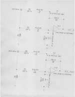
The second circuit I do not understand where the +/- legs are for the output..
Which circuit would you use and what improvements can we make?
I'll bread board the next unit and then have a professional board done when I'm happy.
The criteria is super low Thd and noise. I intend to use this line drive in both my car and home( I got a long cable runs in both and my gear will accept balanced inputs). I've searched the forums but I must be looking in the wrong place I guess. I want to isolated I/O to eliminate as much noise as possible and ground contamination and a minimum gain of 12 db.. my pres only put out between 1-2 V.
Thanks for time in advance.
BUBBA the electrified gearhead.
PS I have samples of AD8599, LM4562, OPA1642, TLE2072 and 1 set of OPA627 and opa1612 I assume a 10K input impedance would be "normal and 600ohm on the outputs?
Everything I've read and from some previous circuit swapping has me favoring the 8599 but I may be totally clueless here.
Attachments
Last edited:
oops
ok been studying this and I need help..I;m not sure what would constitute the best balanced circuit, but I realized one of my circuit scans sucked so I'm reposting it. really just need some general guidance.. I'm not a circuti designer but I can do good board layout, understand the basics of decoupling and filter caps and general stuff but actually making the circuits work..I'M LOST..thanks
ok been studying this and I need help..I;m not sure what would constitute the best balanced circuit, but I realized one of my circuit scans sucked so I'm reposting it. really just need some general guidance.. I'm not a circuti designer but I can do good board layout, understand the basics of decoupling and filter caps and general stuff but actually making the circuits work..I'M LOST..thanks
Attachments
read Walt Jung, ESP, Jensen, Pass diy, D.Self for information about why balanced impedance connections are used, how to achieve them and what to avoid.
Your second circuit is not balanced , but single ended out.
Your first circuit is OK but not a true balanced but a differential output. It will do unfunny things when an output is grounded.
Check the Analog Devices SSM-2142 (or sim. parts) and their app notes on it.
E
Your first circuit is OK but not a true balanced but a differential output. It will do unfunny things when an output is grounded.
Check the Analog Devices SSM-2142 (or sim. parts) and their app notes on it.
E
I DID PROBLEM SOLVED..THANKS LUKUS!!!!
YES I DO PRO GEAR..A I undertstand the need for balanced impedence, THAT'S WHY THE FIRST CIRCUIT HAD ME KINDA BAFFLED.
yes I posted the wrong circuit on the 2nd one.. one output would mean single ended right>>LOL thanks for the ref to the AD-SSM too..I'll read that.!
thanks guys.
YES I DO PRO GEAR..A I undertstand the need for balanced impedence, THAT'S WHY THE FIRST CIRCUIT HAD ME KINDA BAFFLED.
yes I posted the wrong circuit on the 2nd one.. one output would mean single ended right>>LOL thanks for the ref to the AD-SSM too..I'll read that.!
thanks guys.
- Status
- Not open for further replies.