Hi!
This is my first post and I would like to show you the circuit and concept of my balanced phono preamplifier (MM), and ask some advise. It is mostly based on the design of Morgan Jones and SY's His Master's Noise preamplifiers. For low noise the tubes are high gm D3a-s with split passive RC equalisation networks. The balanced design is 3dB noisier than the single ended, at the first stage there are 2 paralelled tubes, that decrease the noise by 3dB, so the first stage is as noisy as the single ended version. The first stage is transformer coupled to the second stage. I think at the first stage, where noise is the most critical, transformer has some advantages.
- Lower DC resistance and lower Jonson noise (but I know this is marginal)
- Lower HT is lower noise from the power supply (I will use the Morgan Jones statistical regulator)
- CMMR of the transformer decrease the common mode noise from the HT and long tail CCS
- No need of high value coupling capacitor
Do you think I am right or do I miss something and it does not worth it? Lundahl or Monolith magnetics IT transformers are a bit expensive. Because of the low signal level I suppose, I have to make a mumetal shield as well. I have to balance the transformer for zero DC imbalance by a trimmer potmeter in the cathodes, that inject some noise, but I would use a trimmer made from SMD resistors, like any volume control, so I think it would be not a problem. I have not calculated the exact values for the RC network yet, I have not decided what capacitor I will use.
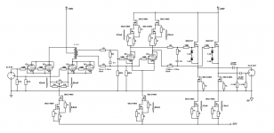
Here is the circuit, the pdf file is nicer.
This is my first post and I would like to show you the circuit and concept of my balanced phono preamplifier (MM), and ask some advise. It is mostly based on the design of Morgan Jones and SY's His Master's Noise preamplifiers. For low noise the tubes are high gm D3a-s with split passive RC equalisation networks. The balanced design is 3dB noisier than the single ended, at the first stage there are 2 paralelled tubes, that decrease the noise by 3dB, so the first stage is as noisy as the single ended version. The first stage is transformer coupled to the second stage. I think at the first stage, where noise is the most critical, transformer has some advantages.
- Lower DC resistance and lower Jonson noise (but I know this is marginal)
- Lower HT is lower noise from the power supply (I will use the Morgan Jones statistical regulator)
- CMMR of the transformer decrease the common mode noise from the HT and long tail CCS
- No need of high value coupling capacitor
Do you think I am right or do I miss something and it does not worth it? Lundahl or Monolith magnetics IT transformers are a bit expensive. Because of the low signal level I suppose, I have to make a mumetal shield as well. I have to balance the transformer for zero DC imbalance by a trimmer potmeter in the cathodes, that inject some noise, but I would use a trimmer made from SMD resistors, like any volume control, so I think it would be not a problem. I have not calculated the exact values for the RC network yet, I have not decided what capacitor I will use.
Here is the circuit, the pdf file is nicer.
Attachments
I would like to show you the circuit and concept of my balanced phono preamplifier (MM)
In the first stage, should the two grid resistors both go to the input, instead of being in series?
I like the idea of only one coupling capacitor per phase. Is that a 1:1 transformer?
Last edited:
Why not simply amplify the 5(?)mV input to a sturdy 1V with a couple of low noise FETs? A summing amplifier made from a coupled cathode triode pair can act as a buffer. Or, first run the RIAA correction to have over time stable Rout.
SYs equal opportunity MM is a much nicer approach to balanced phono. You must minimise capacitance for MM use.
SYs equal opportunity MM is a much nicer approach to balanced phono. You must minimise capacitance for MM use.
Is there a way to see the article without buying the digital copy of Linear Audio vol. 7 and 8? From what I understand it uses a modified topology shared with his Syclotron, but I've never seen much else, and the pics are broken in the original thread-
"Equal Opportunity" MM Pre
EDIT: found it-
Downloads | Linear Audio
Also pasted here so it's easier to find.
Looks interesting, very busy with silicon like most of his designs for lower signal levels.
Attachments
Last edited:
full articles are €6 which is worth the price IMO All articles | Linear Audio
It's not for the tube only purist mind.
It's not for the tube only purist mind.
3 constant current circuits to determine two currents in the LTP? How can that work? Surely a current mirror anode load is needed here? Or is this just because the RIAA network is missing at the moment?
Why FETs for the current sources/sinks?
Why FETs for the current sources/sinks?
Thank you for your comments.
I did not mentioned, but I will use the MM preamp with MC cartridge and MC transformer, so input capacitance is not a problem. But the D3a-s has about 210pF Miller capacity, 2 in parallel and they are in series by the balanced design, so the input capacity is 210 pF.
I have couple of D3a-s so I would like to use them, that's why I made this tube circuit.
In the second stage the 3 ccs should work, the 2 ccs in the anode just an active load, making the loadline horizontal. But it could be BJT or current mirror also. I do not know the high voltage current mirror works better here, than the ccs.
First I just do not know if the transformer (1+1:1) is a good idea or just waste of money and a resistor or ccs is the same good?
I read in this thread, that Vinylsavor likes transformer coupling for LCR equalisation network. (But I know RC network does not need 600 Ohm impedance and step down transformer.)
Phono stage design considerations part 1: choosing 1st stage tube
In the second stage the 3 ccs should work, the 2 ccs in the anode just an active load, making the loadline horizontal. But it could be BJT or current mirror also. I do not know the high voltage current mirror works better here, than the ccs.
Because the 2 current sources will not exactly sum to the current sink value, those LTP outputs will latchup.
OK, I understand. I just did not want to make the second stage too difficult.
I was thinking to make the second stage a mu-follower, but I have to use just too many tubes and elevated heater power supply.
But then a gyrator loaded differential pair would be a good solution? The low output impedance would eliminate the change of the plate resistance with tube ageing.
I was thinking to make the second stage a mu-follower, but I have to use just too many tubes and elevated heater power supply.
But then a gyrator loaded differential pair would be a good solution? The low output impedance would eliminate the change of the plate resistance with tube ageing.
- Home
- Amplifiers
- Tubes / Valves
- Balanced IT coupled phono preamp