Thank you all for your contributions.
I have done the following:
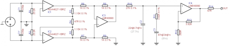
- moved the JFET ADA4627-1BRZ to the input
- my MM cartridge (Ortofon Blue) nominal output is 5.5mV, but to my surprise I have measured peaks up to 75mV on the oscilloscope
- the first stage gain was increased to 50x (+34dB), the datasheet says it will remain constant to 30kHz
- the increased feedback resistors also reduce the load on that stage
- the output stage gain was reduced from 23x to 11x (+21dB)
- the op amps can swing at least 12v peak with +/-15V supply, so clipping should not occur
- the total preamp gain is +34dB -20dB + 21dB = 35dB
- the output impedance of the second stage into the RIAA network up to 20kHz seems to be negligible
- I have precisely adjusted the RIAA values with the KAB calculator recommended by SY
- split input load capacitors for increased HF CMRR
Of course each op amp will have good power supply bypass caps. I plan to do this with SMD components.
Anything else that should be modified?
Can I use C0G SMD capacitors in the RIAA network? Are they good enough for audio? Or should I stick to (physically much bigger) film caps?
I have done the following:
- moved the JFET ADA4627-1BRZ to the input
- my MM cartridge (Ortofon Blue) nominal output is 5.5mV, but to my surprise I have measured peaks up to 75mV on the oscilloscope
- the first stage gain was increased to 50x (+34dB), the datasheet says it will remain constant to 30kHz
- the increased feedback resistors also reduce the load on that stage
- the output stage gain was reduced from 23x to 11x (+21dB)
- the op amps can swing at least 12v peak with +/-15V supply, so clipping should not occur
- the total preamp gain is +34dB -20dB + 21dB = 35dB
- the output impedance of the second stage into the RIAA network up to 20kHz seems to be negligible
- I have precisely adjusted the RIAA values with the KAB calculator recommended by SY
- split input load capacitors for increased HF CMRR
Of course each op amp will have good power supply bypass caps. I plan to do this with SMD components.
Anything else that should be modified?
Can I use C0G SMD capacitors in the RIAA network? Are they good enough for audio? Or should I stick to (physically much bigger) film caps?
Attachments
COG is absolutely great for audio and just as good as pp, witb the added advantage of much smaller size.
What I don't get is why you changed the input opamp to ada4627. LME49990 appears to be superiour in all respects.
What I don't get is why you changed the input opamp to ada4627. LME49990 appears to be superiour in all respects.
Hi,
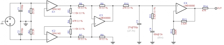
have You considered the OPA140/2140/4140yet?
It's a new familiy of JFET input OPAmps that feature very promising specs.
The combination of very low voltage noise, lowest current noise and very low input offset is quite unique and would allow to use the 140s for all stages of the MM preamp.
One could use for example one OPA4140 for IC1 to IC4.
Or for IC1, IC2 and IC4 and(!) a additional DC-Servo stage.
Or a OPA2140 for IC1 and IC2 only.
Using COG/NPO caps and all SMD devices a tiny layout, almost a headshell preamp could be built.
jauu
Calvin
Calvin, tnx for the opa140 allert, new to me. Looks like a somewhat improved 134. Psrr not that stellar though.
edit, I would probably only use it at line level, not for phono preamp, noise a tad high for that.
edit, I would probably only use it at line level, not for phono preamp, noise a tad high for that.
Last edited:
Using COG/NPO caps and all SMD devices a tiny layout, almost a headshell preamp could be built.
jauu
Calvin
Calvin, sorry to barge in like that, I was just fretting about what type of SMD decoupling to use in my project. I know NP0 are very low loss and stable, but they are 5 x or more expensive than say XR7. Is there an advantage to use NP0 for decoupling?
Jan
What I don't get is why you changed the input opamp to ada4627. LME49990 appears to be superiour in all respects.
Well, Calvin and mlloyd1 told me that there are better choices for the first stage...
For MCs the 49990 seems a good choice, but at the elevated impedance levels of MM carts JFET input OPAmps may give lower noise and add the advantage of virtually no iput bias and input offset currents.
Calvin - the OPA140 looks good and it is not very expensive.
Hi,
@vacuphile:
Looking only at en, the noise voltage figure doesn´t show the full picture.
Indeed it could terribly mislead one.
You need to keep an eye on the 1/f frequencies and the in the noise current figure too.
For impedances below ~2kOhm the voltage noise figure dominates.
Then it´s mostly a matter of a low 1/f frequency that discrimantes against two OPAmps.
Above ~5kOhms the noise current dominates.
Again the lower 1/f frequency beeing better.
Over the range between ~2k and 5k cvoltage and current noise weigh roughly the same.
Now MM carts internal impedances may be viewed as a series RL-connection with rising impedance.
The popular 3600 Body from Audio Technica (AT95 et al) is specced at 410R/400mH/2k8@1kHz.
The AT440MLA, 780R/490mH/3k2@1kHz.
Ortofons 2M series, ??R/630-700mH/1k3@1kHz.
Referenced to 1kHz most MMs fall into the range from >1kOhm to ~3kOhm
If the Phonostage features a high input impedance and the cart is shunted by a 47k resistor to gnd, then the source impedance seen by the input stage raises with rising frequency to just below 47k.
So while a input stage with low en figure shows lower noise at lower frequencies, a input with low in figure shows lower noise at higher frequencies.
IIrc the rule of thumb values for ´noise transparency´ are <5nV/sqrHz and <1pa/sqr Hz, both @1kHz.
Those are values the old NE5534 and OP27 (the OP27 having considerably lower 1/f figure) match very well ... which is one of the reasons why they have been quite popular with phono input stages.
OPAmps like the LME49990 that feature extremely low en figures are typically optimized for low source impedances and become noisy at higher source impedances due to their relatively high in figures (2.8pa/sqrHz, against 0.4pA/sqrHz of a NE5534A/OP27).
If You feel still uncomfortable with the voltage noise figure of the OPA140, then You may choose the old AD745 instead, but only available as Single OPAmp in DIP-8 and SOIC-16.
@Jan
XR7 are perfectly ok for power rails decoupling.
COG/NPO may be well used for the audio signal path/RIAA components.
The OPA140 features a set of specs I haven´t seen before in a quite cheap JFET input OPAmp.
With an en of 5.1nV/sqrHz it´s voltage noise is just low enough for MM carts.
The 1/f frequency which is typically higher with FETs than with bipolars is clearly lower than the NE5534´s, and similar to the LME49990´s.
Its current noise figure slaps any bipolar OPAmp right in the face at vanishingly low 0.8fA/sqrHz.
The input offset voltage figures are also typically higher with FET inputs.
But the OPA140 series shows exceptional low values here too.
They do preserve the low input bias currents of FETs (just leakage), which allows to directly couple the delicate pickup coils.
The input bias currents of bipolar OPAmps can reach values close to the range of the pickup´s signal currents and may require large valued coupling caps.
PSRRR is more than sufficiently high.
Remember that the power rail decoupling even with small-sized caps is very effective above 1kHz.
The Gain-bandwidth product is rather small after todays standards, but this ain´t no disadvantage her.
First, no one needs excessively high bandwidths/GBPs in vinyl audio and
second, does it ease power supply decoupling and lowers risk of oscillation.
A OPAmp needs to be blocked on its supply rails over its entire GBP.
This makes the layout of the PCB critical.
A GBP of 11MHz requires certainly less care and effort than 110MHz.
jauu
Calvin
Last edited:
Calvin,
Very clear, thanks. I will start using OPA140 for active filters once I am through my stack of LM4562's. I don't like their susceptibility to RFI, they tend to pick up the telephone before it even rings :-(
Very clear, thanks. I will start using OPA140 for active filters once I am through my stack of LM4562's. I don't like their susceptibility to RFI, they tend to pick up the telephone before it even rings :-(
Hi,
still no measurements against Offsets.
No blocking cap, no DC servo.
Also, no means to vary input stage loading.
MM pickups almost always require tuning of the capacitive load.
jauu
Calvin
still no measurements against Offsets.
No blocking cap, no DC servo.
Also, no means to vary input stage loading.
MM pickups almost always require tuning of the capacitive load.
jauu
Calvin
Last edited:
Hi,
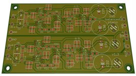
For the input stage load, I have provided place for socketable, easily replaceable capacitors on the PCB. I already know what C load I need (I have built and tested the non-balanced DC coupled preamp from the LM4562 datasheet).
The next stage in my preamp can tolerate a little offset, but I will try to measure exactly how much offset there is and I'll decide if I can live with it or not...
what does this mean and what steps need to be taken to counteract the effect?A OPAmp needs to be blocked on its supply rails over its entire GBP.
This makes the layout of the PCB critical.
what does this mean and what steps need to be taken to counteract the effect?
Effectively bypassed to ground. Layout, design, parts selection.
but he uses the correct word in the previous sentence.For a non-native English speaker, he does extremely well.
does it ease power supply decoupling and lowers risk of oscillation.
implying he means something different between blocked and decoupling.A OPAmp needs to be blocked on its supply rails over its entire GBP.
Last edited:
That describes me.
I struggled and persevered with english at school.
I gave up two "other" languages as soon as I was allowed.
I struggled and persevered with english at school.
I gave up two "other" languages as soon as I was allowed.
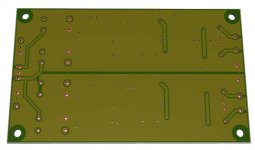
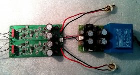
Prototype built and working, turntable rewired to balanced. 🙂
There is only 32mV of offset on each channel, I can live with that.
This thing makes music, it sounds better than my previous phono pre (the one from the LM4562 datasheet). The background is completely black and silent.
I'm very happy with it, thanks to those who helped! 🙂
Vincent
There is only 32mV of offset on each channel, I can live with that.
This thing makes music, it sounds better than my previous phono pre (the one from the LM4562 datasheet). The background is completely black and silent.
I'm very happy with it, thanks to those who helped! 🙂
Vincent
- Status
- Not open for further replies.
- Home
- Source & Line
- Analogue Source
- Balanced input phono preamp