Hi,
I need a simple but good balanced input MM RIAA preamp.
I have already built the unbalanced preamp in the LM4562 datasheet and it sounds good, so I thought about replacing the first stage of that schematic with a balanced instrumentation amplifier with a gain of 24.6x...
Can you knowledgeable guys please take a look at the schematic and confirm that this should work OK before I start building? Thanks.
Attachments
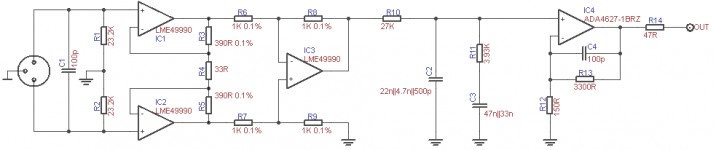
only overview........i have not simm'd this schematic.
there are designs (tda3420 and so...) that do not use the ground connection between the two input res (23k).........use it or not - two possibilities.
i would have a look at the offset at the output of this preamp........a cap in the signalpath can help..........for safety.
there are designs (tda3420 and so...) that do not use the ground connection between the two input res (23k).........use it or not - two possibilities.
i would have a look at the offset at the output of this preamp........a cap in the signalpath can help..........for safety.
While I guess that would work, I'm not sure about the RIAA accuracy. The output impedance of the first stage is relevant here, some trimming might be needed.
EDIT: and of course mjf is right, DC is always an issue with high gain circuits.
EDIT: and of course mjf is right, DC is always an issue with high gain circuits.
You are right about the DC , I will check the offset. However I will use a tube buffer after this stage, and this tube stage really doesn't care for +/-1v bias difference.
My main concern is indeed the RIAA acuracy. I don't know what the first stage output impedance is, but the RIAA filter was designed for the output impedance of a LM4562 gain stage, and I hope the difference is small enough to be swamped by the 27K resistor...
My main concern is indeed the RIAA acuracy. I don't know what the first stage output impedance is, but the RIAA filter was designed for the output impedance of a LM4562 gain stage, and I hope the difference is small enough to be swamped by the 27K resistor...
Y
My main concern is indeed the RIAA acuracy. I don't know what the first stage output impedance is, but the RIAA filter was designed
for the output impedance of a LM4562 gain stage, and I hope the difference is small enough to be swamped by the 27K resistor...
For 0.1% error, the small signal source impedance should be less than 27 Ohms. This should be no problem with an op amp gain of 1.
Hi,
a balanced input is useful for MC carts.
MMs are often de-balanced by a gnd connection of one of the four signal pins.
A balanced input wpukd not be required for these carts.
For MCs the 49990 seems a good choice, but at the elevated impedance levels of MM carts JFET input OPAmps may give lower noise and add the advantage of virtually no iput bias and input offset currents.
As MC stage the input resistors needed to be lower than 2x 23k2.
To correct for DC offset You could cut the gnd connection of R9 and feed the servo signal into that node.
A possible offset of the second stage is typically negligible.
I wonder though why You choose a three OPAmp structure instead of using a integrated INA like TI's INA103 or 163, or THAT1570 et al.
See for example this Thread
You find another example on my website.
jauu
Calvin
overall, i guess i agree with a lot of calvin's comments.
although conceptually, your proposal will work , i think you could choose a better fitting opamp than the lme49990 for the front end to a moving magnet cartridge.
also, i did not check resistor values for gain distribution - you need to balance that with noise and overload margin.
good luck and keep posting as you go along ...
mlloyd1
Thanks a lot for your comments, much appreciated!
Indeed, I will have to rewire the internals of my turntable... the cartridge is an Ortofon Blue.
I had no idea such a device existed. 🙂 I have already designed a PCB, so I guess I'll stick to the three opamp structure...
Should I move the ADA4627 to the input? Or can you guys recommend another one?
Thanks!
MMs are often de-balanced by a gnd connection of one of the four signal pins.
Indeed, I will have to rewire the internals of my turntable... the cartridge is an Ortofon Blue.
I wonder though why You choose a three OPAmp structure instead of using a integrated INA
I had no idea such a device existed. 🙂 I have already designed a PCB, so I guess I'll stick to the three opamp structure...
at the elevated impedance levels of MM carts JFET input OPAmps may give lower noise
i think you could choose a better fitting opamp than the lme49990 for the front end to a moving magnet cartridge.
Should I move the ADA4627 to the input? Or can you guys recommend another one?
Thanks!
Should I move the ADA4627 to the input? Or can you guys recommend another one?
sure, one idea is to change IC1 & IC2 to low noise JFET input op amps.
however, i now see that you're loading them with kinda' low value resistors (for lower noise of course, quick eyeball guess looks like about 300ohms net load each) to set the gain. with low impedance loads, the gain drops, linearity worsens, your DC parameters probably worsen too, etc. so now the engineering judgement comes in to decide how small is "too small" and how big is "too big"?
or, you could hang power buffers at the back of each input amp and use smaller resistors and maintain your distortion and DC performance, might loose a little noise performance, have to pay more attention to compensation, your cost and parts count goes up, your layout challenges increase, etc.
oh yeah, that's right, you'll have to be careful about layout and bypassing - needs to be really good with low noise and high currents running around in the same place, it could get ugly ...
isn't this fun?
🙂
Oh boy, this is less straightforward than I thought it would be. 🙂
Actually, it's very straightforward.
1. Use an input stage with low current noise as well as low voltage noise. It's likely to be a FET input opamp.
2. Calculate overload margins at spot frequencies between 20Hz and 20kHz; adjust your gain structure accordingly- HF overload margins are more important than LF because of the velocity response of the cartridge and the nature of mistracking.
3. An all-in-one-go passive between two flat gain blocks works wonderfully well if you can get at least 30-40bB of gain out of the first stage. Use a standard topology if you want good conformance; the calculator at KAB is terrific for this. Your instincts about the series resistor swamping the effects of op-amp source impedance are right on, but it's worth an hour or two of your time to trim that resistor for conformance and inter-channel matching after you have the circuit up and running.
4. If the cartridge has a grounding strap, 20 seconds with a razor blade will fix that. I've only seen these on Shures, but I haven't seen every cartridge out there. Voila, balanced outputs!
5. You generally don't have to worry about rewiring the tonearm or turntable, but you'll want balanced interconnects and connectors. I recommend thin, low-noise microphone cable and REAN Tiny XLR.
6. Grounding, grounding, grounding. Bill Whitlock's papers are your friend.
What you're doing here is tackling an actual problem rather than the all-too-common imaginary ones. Having done this and heard the results of going balanced for MM and MC, I would never go back. The noise immunity is remarkable; my favorite demo is to turn up the volume and touch the cartridge pins with my finger.
Good luck!
Sy, I know you have balanced using transformer input, but have you compared that to active circuitry? I love balanced audio. Extremely slanted this way. The phono stage is my next adventure and your phono is one of the few that take this route. I now see Calvins op amp version. Any othe discrete input stages that might offer something similar?
I use transformers for MC. For MM, they do not work well- my balanced MM circuit (The Equal Opportunity) is in Linear Audio vol 7 and 8, and does not use transformers. The tradeoff is complexity and the need for parts matching, but the performance is very good.
There's a thread about the EO pre somewhere around here....
There's a thread about the EO pre somewhere around here....
In addition to the other remarks made, I would split C1 into two caps going to ground. In you schematic, common mode RFI is not shunted to ground.
Sorry, my post was off topic. I have an MC cartridge. Have you compared input transformers.
Only three of them. The Sowter I ended up with worked best of that group, with outstanding CMR. I would love to try a 1:10 Jensen, but...$$$$.
Now it works. What is the source impedance needed for this network?
Yeah... what source Z?
- Status
- Not open for further replies.
- Home
- Source & Line
- Analogue Source
- Balanced input phono preamp