You might want to go to:
http://www.analog.com/library/analogDialogue/archives/39-05/op_amp_applications_handbook.html
and download section 6.
There is a lot of great information, there, about balanced audio line receivers.
Maybe something like Figure 6-33 would be good, which is a line transformer buffered by a simple differential line receiver. Otherwise, maybe Figure 6-30. Figure 6-26 is also interesting.
- Tom Gootee
http://www.fullnet.com/~tomg/index.html
-
BWRX said:
It doesn't escape from feedback influencing the input impedances unequally. In fact, the two input impedances can't be matched. But this configuration does what you were looking to do - convert an unbalanced or balanced signal to a balanced signal in a relatively simple way,
Ah, OK. That's what I thought. Much like the ESP solution: "Not strictly correct, but no more practically flawed than most aspects of any given real-world design".
For my purposes, a $38 high-end transformer also counts as 'simple change' in that it adds only one passive. $38! I had originally completely discounted even looking at transformers because I had expected them to be $300+!
BWRX said:
Here is a schematic of the instrumentation amp in this post: http://www.diyaudio.com/forums/showthread.php?postid=1049141#post1049141
I had suggested replacing IC1 with the input transformer and loading resistors but you can keep the differential buffer and add the input transformer and loading resistors in front of it too. That configuration would have excellent common mode rejection.
Thank you much for the pointer. I had in fact seen the thread before, but didn't know that was the one being referred to. I originally thought 'BWRX' was an amp design as opposed to a username.
gootee said:
Maybe something like Figure 6-33 would be good, which is a line transformer buffered by a simple differential line receiver. Otherwise, maybe Figure 6-30. Figure 6-26 is also interesting.
Oh, 6-33 *is* tantalizing... in that diagram, could U1 simply be the 3886, or does that run into the same problem of having the output influencing the impedence on the negative input? Or does it not matter because both sides are being driven by the transformer?
[edit: I meant 6-33 not 6-30]
xiphmont said:Oh, 6-33 *is* tantalizing...
That's exactly the configuration I was describing back in post #9. And yes, U1 would be the LM3886 with external feedback resistors.
BWRX said:
That's exactly the configuration I was describing back in post #9.
I see that now :-| :-(
Does the differential (not quite balanced) input actually give me anything here? The single-ended version (that is, the balancing transformer is feeding the 3886 as a single-ended amp) is inside the case with the input transformer an inch away from the + input. It is only single ended for that distance.
It seems like the differential version (transformer feeding differential inputs rather than + and siggnd) is just going to require better balanced resistors (ie, be a pain).
The single-ended gainclone kit doesn't bother to balance the branches. The input side is 1k/22k and the output 680/22k! The reference sheet's 'Typical Application' doesn't even pretend to set up a symmetrical positive input (R2 is missing entirely). So... for my purposes... it looks like single-ended non-differential is actually better. The single-ended does not care about balance at all (or is that just because there's no point in caring-- it's that much worse?)
The original point of a balanced input was CMNR to the box, not pursing an ideal of balanced signal path all the way to the chip. So unless I screw up with wire/component placement, the single ended 3886 configuration should be just as good as the differential, yes?
[edited for more thinking]
[edited again for much more thinking]
The differential configuration gives you better common mode rejection and lower output offset. The common mode rejection figures do depend on how well the resistor pairs are matched. The closer they are the better the CMR will be. Matching the resistors isn't that difficult. You can buy 0.1% tolerance resistors or match them as close as possible with a multimeter.
I can't say for sure which configuration would sound better because everyone has a different set of ears 🙂 If it were my choice and I had a balanced source I would definitely try the LM3886 as a differetial amp with input transformer.
I can't say for sure which configuration would sound better because everyone has a different set of ears 🙂 If it were my choice and I had a balanced source I would definitely try the LM3886 as a differetial amp with input transformer.
BWRX said:The differential configuration gives you better common mode rejection and lower output offset. The common mode rejection figures do depend on how well the resistor pairs are matched. The closer they are the better the CMR will be. Matching the resistors isn't that difficult. You can buy 0.1% tolerance resistors or match them as close as possible with a multimeter.
I can't say for sure which configuration would sound better because everyone has a different set of ears 🙂 If it were my choice and I had a balanced source I would definitely try the LM3886 as a differetial amp with input transformer.
...at what point would the resistor mismatch affect CMR such that it's no longer better than single ended? This is mostly a question of idle curiosity. (And in fact-- most of the inputs will be pseudobalanced or direct-balanced). Also, when you say 'improve the CMR', you're talking about the CMR of just the amp input or of the the transformer too? The input transformer should already be providing an additional 70dB-120dB of CMR even into a single-ended amp input according to the cinemag and Jensen application notes. I thought the transformer was, in some ways, a *replacement* for the CMR of the amp.
The other problem---where would the attenuator pot go? I really don't like the idea of radically altering the input impedence (shunt mode attenuator on the source side of the transformer). I really don't trust my sources enough to try to pull that.
Stab in the dark-- shunt mode across the differential inputs to the 3886? There's gotta be something elegant that isn't too huge a tradeoff....
All the above referring to the schematic in figure 6-33:
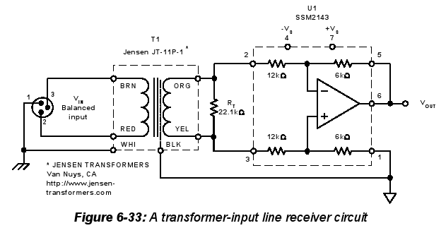
...with values altered to suit the design (about 10k/220k instead of 12k/6k). Hmm, would this topology/value change affect the original output Zobel?
[edit: more questions about CMR and Zobel]
Hi,
that last schematic could have your chipamp in there instead of the ssm2143. Just add the 0.1% matched resistors and adjust them to give the gain you require.
As for volume.
Insert series resistors in between each of the xlr poles to each of the transformer inputs.
Then insert the variable resistor(or even a twelve way switched resistor) after the series resistors. Now you have a balanced input and volume control and no extra chips nor extra expensive components.
The series resistors could be 1k0 to 10k depending on whether your balanced source can drive 600ohm load. If not then the higher value would be suitable.
xiphmont said:
...at what point would the resistor mismatch affect CMR such that it's no longer better than single ended? This is mostly a question of idle curiosity. (And in fact-- most of the inputs will be pseudobalanced or direct-balanced). Also, when you say 'improve the CMR', you're talking about the CMR of just the amp input or of the the transformer too? The input transformer should already be providing an additional 70dB-120dB of CMR even into a single-ended amp input according to the cinemag and Jensen application notes. I thought the transformer was, in some ways, a *replacement* for the CMR of the amp.
See Figure 2.2, and Equations 2-2 and 2-2, in section 2 ("Specialty Amplifiers") at the link I gave for the Op Amp Application Handbook. It looks like for 0.1% tolerance resistors, the worst-case dc CMR would be 66dB, but with some assumptions. With three 0.1% resistors and one mis-matched by 1%, CMR drops from 66dB to 46 dB.
Those figures assume R1=R2, and that the amplifier's CMR > 100 dB. For other R values, see the cited equations.
And note that it's actually the RATIOS of the two resistors in each leg that need to match closely. i.e. The top two resistors' ratio needs to match the bottom two resistors' ratio.
You can get IRC 0.1% resistors, 25ppm/degC (as opposed to 50ppm for the common 1% metal film type), for less than $1.00 qty 1, at http://www.mouser.com . Those 25ppm/degC ones have part numbers like 66-RCLF-D-value, at mouser.com, IIRC. There are also some others, there, that have 5 and 10 ppm/degc tempcos, but aren't offered with nearly as many values.
- Tom Gootee
http://www.fullnet.com/~tomg/index.html
-
gootee said:
See Figure 2.2, and Equations 2-2 and 2-2, in section 2 ("Specialty Amplifiers") at the link I gave for the Op Amp Application Handbook. It looks like for 0.1% tolerance resistors, the worst-case dc CMR would be 66dB, but with some assumptions. With three 0.1% resistors and one mis-matched by 1%, CMR drops from 66dB to 46 dB.
OK, so you are in fact talking about additional CMRR provided by the amp *over* the CMR provided by the transformer. The transformer is already handing me 120dB of DC rejection (less at HF). It seems like going for more is a bit unwarranted; I better not have common mode noise greater than 0dB to worry about!
(In my case, 'long runs' are 50 feet of signal level at home, not 500 ft of mic level run in a theater space with a messed up power grid shared with 500kW of dimmerpacks. In the theater, I'd probably want more then 120dB of CMR).
Again, thinking aloud not arguing, I'd like to know if I'm wrong there.
Let me tie all the threads so far together and post a new schematic. As always, this is thinking aloud and I want to hear when I'm wrong.
Point 1: transformer into single ended or pseudobalanced
Most people running Gainclones as 'super high fi' amplifiers are doing so single ended and as such have a low CMRR (somewhere from 0 to 30dB-ish). Because these are going to be in self-powered monitors, the line level runs will be a little longer, and so a little more hum/buzz rejection is needed. The Cinemag CMLI-15/15B is being used as an isolation and rejection stage. The idea is that it gives substantial enough improvement over a naked single-ended input that the additional noise rejection of going to a differential/pseudo-balanced topology doesn't make much sense in the context of the rest of the system mostly because it complicates the placement of an attenuator.
Point 2: attenuator placement
Assuming a single-ended input and attenuator on the input, as is illustrated in the NatSemi application notes and as configured in the majority of gainclone kits, the wiper 'lifting', either through poor design or age of the pot (think about the scratchiness potentiometers develop with age) will cause swings in the output DC offset. The concern is not that it will damage the speakers, but that even a relatively small DC offset will cause alot of noise as the pot ages, and that noise is in proportion to the max DC offset not the input program. It will be loud, even if the amp is 'idle'.
A few solutions have been offered:
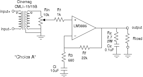
a) Choose not to care. This is a popular solution as the majority of the small kits go this route. Don't use an attenuator, or use the best one you can afford. Replace it if it gets icky. Potentiometer noise once it shows up is annoying but not going to damage anything; a scratchy potentiometer is going to be noisy anyway. Optional Ci reduces the liability further by cutting down the output offset by 30dB.
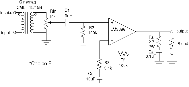
b) Run the circuit as-is in the NatSemi notes but decouple the + input by replacing R1 with a coupling cap and make sure R2 is there to provide a path for bias current to ground. Disadvantages: another capacitor in the signal path (is this *really* something people care about with good modern capacitors?) Advantages: Input completely isolated from bias current changes, can be trimmed to near-zero offset. (Hmm, C1 and Ci are insanely large given the resistor values, aren't they?)
c) shunt-mode attenuator in front of the transformer. I'm going to reject this one straight out because of the inherent impedence/attenuation tradeoff on the input (either you have large impedence swings, or you have alot of inherent signal loss through attenuation) and the fact that the Cinemag transformer's design notes state explicitly that the transformer wants to be 'looking into' a low impedence. Adding the shunt attenuator in front of the transformer gauarntees the source will appear to be high impedence.
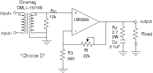
d) Use a potentiometer shunt-mode as a gain-pad, not an input attenuator. That is, the potentiometer replaces Rf1 and directly alters the circuit gain rather than altering the input attenuation. Disadvantages: can only reduce gain down to unity, not below. In my circuit, it has a 0dB to 30dB range. Advantages: eliminates several passives, S/N is just as good at low gain as at high gain.
(Actually, it's not entirely clear to me that this greatly reduces the output offset voltage swing on noisy pot, just that it simplifies the circuit if you're willing to give up 'attenuation' range. Can somone convince me choice D actually gives me nothing?)
Point 1: transformer into single ended or pseudobalanced
Most people running Gainclones as 'super high fi' amplifiers are doing so single ended and as such have a low CMRR (somewhere from 0 to 30dB-ish). Because these are going to be in self-powered monitors, the line level runs will be a little longer, and so a little more hum/buzz rejection is needed. The Cinemag CMLI-15/15B is being used as an isolation and rejection stage. The idea is that it gives substantial enough improvement over a naked single-ended input that the additional noise rejection of going to a differential/pseudo-balanced topology doesn't make much sense in the context of the rest of the system mostly because it complicates the placement of an attenuator.
Point 2: attenuator placement
Assuming a single-ended input and attenuator on the input, as is illustrated in the NatSemi application notes and as configured in the majority of gainclone kits, the wiper 'lifting', either through poor design or age of the pot (think about the scratchiness potentiometers develop with age) will cause swings in the output DC offset. The concern is not that it will damage the speakers, but that even a relatively small DC offset will cause alot of noise as the pot ages, and that noise is in proportion to the max DC offset not the input program. It will be loud, even if the amp is 'idle'.
A few solutions have been offered:
a) Choose not to care. This is a popular solution as the majority of the small kits go this route. Don't use an attenuator, or use the best one you can afford. Replace it if it gets icky. Potentiometer noise once it shows up is annoying but not going to damage anything; a scratchy potentiometer is going to be noisy anyway. Optional Ci reduces the liability further by cutting down the output offset by 30dB.
b) Run the circuit as-is in the NatSemi notes but decouple the + input by replacing R1 with a coupling cap and make sure R2 is there to provide a path for bias current to ground. Disadvantages: another capacitor in the signal path (is this *really* something people care about with good modern capacitors?) Advantages: Input completely isolated from bias current changes, can be trimmed to near-zero offset. (Hmm, C1 and Ci are insanely large given the resistor values, aren't they?)
c) shunt-mode attenuator in front of the transformer. I'm going to reject this one straight out because of the inherent impedence/attenuation tradeoff on the input (either you have large impedence swings, or you have alot of inherent signal loss through attenuation) and the fact that the Cinemag transformer's design notes state explicitly that the transformer wants to be 'looking into' a low impedence. Adding the shunt attenuator in front of the transformer gauarntees the source will appear to be high impedence.
d) Use a potentiometer shunt-mode as a gain-pad, not an input attenuator. That is, the potentiometer replaces Rf1 and directly alters the circuit gain rather than altering the input attenuation. Disadvantages: can only reduce gain down to unity, not below. In my circuit, it has a 0dB to 30dB range. Advantages: eliminates several passives, S/N is just as good at low gain as at high gain.
(Actually, it's not entirely clear to me that this greatly reduces the output offset voltage swing on noisy pot, just that it simplifies the circuit if you're willing to give up 'attenuation' range. Can somone convince me choice D actually gives me nothing?)
Hi,
post 27 shows the balanced input opamp.
Add this topology to pic 3 from post 31.
Now delete the transformer.
You have a balanced attenuator, with balanced chipamp and retain much of the CMRR of the electronically balanced circuit (not quite as good as the isolating transformer, but a lot cheaper and as you explained may be enough for a domestic environment.
Is it worth experimenting with?
If you still reject this option, no hard feelings, it's your amp not mine.
BWRX,
have you added local attenuation to your balanced circuit?
xiphmont said:
(Hmm, C1 and Ci are insanely large given the resistor values, aren't they?)
...and in fact, back of the envelope reactance calculations suggest .2 to 1uF is a better choice (given that the amps will be dedicated to a single driver/aperiodic enclosure their entire lives, and there's no point to a flat response below 40Hz).
Xc = 1/(2pi*f*C), setting f to 8 (40Hz/5) and Xc to 100kOhms, we get C = .2uF
.2uF might even be a good choice for making sure the amp can't push out as much bass below where the driver and air mass decouple and thus serve to limit excursion as well...
Whee, integrated design requirements.
Hi,
C1 can be scaled for F-3db=8Hz. That's OK.
But Ci should be scaled for about half an octave lower, say 5Hz. Ci starts to get very big with just 3k above it (your 10uF value hits this target exactly). or DC couple both input and NFB.
Why do you show the lower leg going to audio ground rather than tying directly to the transformer?
Then you can omit an extra pair of ground connections at the amplifier input.
AndrewT said:Hi,
post 27 shows the balanced input opamp.
Add this topology to pic 3 from post 31.
Now delete the transformer.
You have a balanced attenuator, with balanced chipamp and retain much of the CMRR of the electronically balanced circuit (not quite as good as the isolating transformer, but a lot cheaper and as you explained may be enough for a domestic environment.
Is it worth experimenting with?
In fact I probably will build it for educational purposes.
My fondness for the transformer solution mainly stems from it being an affordable CMRR Solution-In-A-Can(tm). The pseudo balanced circuits with .1% tolerances will give me 40 or 50dB CMRR, and the $38 can gives me 120dB... It seems worth it to me mainly because it does cost me some extra money, but it is importantly also not costing me practically any additional time (this is the tipping point-- time does equal money. All this design work is fun. Sitting down to build a fleet of these things will quickly become monotonous. I can do no real extra work for 40dB or no real extra work for 120dB is how I'm looking at it.)
The transformer does wreak some havok WRT placement of the attenuator. I am currently leaning toward either solution A or B. Solution D was to see if anyone thought it is any better than than A.
[edited for clarity]
AndrewT said:Hi,
C1 can be scaled for F-3db=8Hz. That's OK.
But Ci should be scaled for about half an octave lower, say 5Hz. Ci starts to get very big with just 3k above it (your 10uF value hits this target exactly).
Ah, it 'sees' the 3.1k R3, not the 100k Rf? OK.
AndrewT said:
Why do you show the lower leg going to audio ground rather than tying directly to the transformer?
Then you can omit an extra pair of ground connections at the amplifier input.
Because it's running single ended and these all should reference to ground.
Do you just mean they should be tied together, then tied to ground, or are you suggesting the transformer negative output and NFB lower leg should tie toether and float? I don't see what the point of that would be as the circuit is single-ended... (The Faraday shield still goes to signal ground in any case, yes?)
Hi,xiphmont said:Because it's running single ended and these all should reference to ground.
Do you just mean they should be tied together, then tied to ground, or are you suggesting the transformer negative output and NFB lower leg should tie toether and float? I don't see what the point of that would be as the circuit is single-ended... (The Faraday shield still goes to signal ground in any case, yes?)
look again at post27.
It's a balanced input to unbalanced output.
The gain is set with the integrated resistors built into the SSM package.
Substitute the chipamp for the ssm and select your own resistors to duplicate the schematic.
Now adjust your resistors to get the gain you need and to ensure the chipamp has enough gain to remain stable.
Note that the inputs are NOT connected to ground. The reference leg on the non-inverting connects to ground and it can provide the RF attenuation you can optionally add.
So, yes you can let the inputs float (well almost float, they go all the way back to the source via your balanced interconnect). They then measure and amplify the input signal and don't get contaminated by noisy grounds/shields/etc.
Go to Walt Jung's site and download all his audio articles from the archive. Read all about how to get the best out of opamps (and cascaded opamps) and particularly the tricks to ensuring electronically balanced works as intended.
AndrewT said:
Hi,
look again at post27.
It's a balanced input to unbalanced output.
[...]
Go to Walt Jung's site and download all his audio articles from the archive. Read all about how to get the best out of opamps (and cascaded opamps) and particularly the tricks to ensuring electronically balanced works as intended.
I'm trying to figure out if you're helping me with the single ended designs (eg A/B) or trying to convince me to ditch it and do it another way.
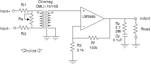
Eg, Are you suggesting something like the following will work?
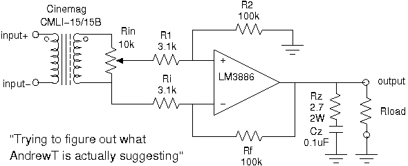
I see that the inputs don't need to reference ground (within limits, they only reference each other), but the above, in which I am attempting to faithfully follow your instructions, does not seem to make any sense.
"the tricks to ensuring electronically balanced works as intended" aren't that interesting since a balanced circuit is not my goal! I'm looking to apply the inherent CMRR of the transformer in a preexisting circuit, avoid mistakes doing so, and if there are any easy freebies that will also improve the noise rejection, I'll apply them too. Tossing out the existing PCBs is not an option I will consider.
I keep saying 'single ended' you keep saying 'you're doing balanced wrong.'
[edit: OK, I lied, Walt's articles on balanced line receivers are interesting (I've read them before) but they're not that useful in direct application to my end goal]
Elaboration on 'does not make sense'--
It makes sense but I'd think the inputs (looking through their 3.1k resistors) would have to be 'driven' by a low impedence source, not the transformer negative and pot wiper.
It makes sense but I'd think the inputs (looking through their 3.1k resistors) would have to be 'driven' by a low impedence source, not the transformer negative and pot wiper.
Hi,
post38 does not look nice.
Not sure if this idea is workable.
add two resistors between the transformer and the pot.
convert the pot to variable resistor.
add two caps//100k
add a third cap across the variable resistor.
The transformer will reflect the source impedance back to this receiver.
post38 does not look nice.
Not sure if this idea is workable.
add two resistors between the transformer and the pot.
convert the pot to variable resistor.
add two caps//100k
add a third cap across the variable resistor.
The transformer will reflect the source impedance back to this receiver.
the title says balanced. You have not confirmed if your source can drive 600ohm.I keep saying 'single ended' you keep saying 'you're doing balanced wrong.'
- Status
- Not open for further replies.
- Home
- Amplifiers
- Chip Amps
- Balanced gainclone sanity check