Hello friends,
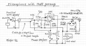
I have recently build 6x microphones as designed by Linkwitz (System Test). I use them to multitrack recording a set of drums. Sound is excellent for the cost of the materials. The problem I get with some of those mics, as when placing one inside the subkick, is that signal clips from time to time the input of my soundcard. It only happens from time to time, say 5 or 6 clips along a 2 minutes recording. I cannot reduce the gain of the opamp because I already potted the pcbs inside the mic enclosures.
Because the voltage swing can be so high, if I reduce it I can record without clipping while the opamp is still able to amplify without clipping itself (it's supplied with +/-9v). So I think I can make an H attenuator using 2x XLR connectors and a piece of cable, and fitting the resistor network inside the plug. I will place the attenuator in the receiving end, so to avoid driving long cables after it. Anyway, they are driving something like 5 meters of balanced cable, so it's not a huge distance.
The microphones are selfpowered with 2x 9v batteries each one. Output is balanced, with a 200 ohm resistor on both hot and cold outputs, as seen in the circuit. The input of the next stage is balanced, a Tascam soundcard stated as 15K in the specs sheet.
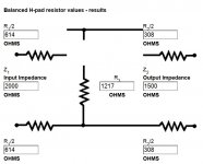
So if I am using this calculator corrently (Passive Audio Attenuators), assuming a 10 ratio of input/output impedance would yield to:
-Input impedance of attenuator: 2000ohm (ten times 200ohm output impedance)
-Output impedance of attenuator: 1500ohm (1/10th of 15000ohm)
-Attenuation required (1-40): 10dB
So the results are shown in the attached picture. Do I have made all the calculations properly?
I am thinking too in fitting a pot in the microphone instead of a fixed attenuator, but due to all the disadvantages of a pot and not needing to "dial in" a precise amount of attenuation, I think I will go with an fixed H pad.
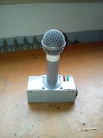
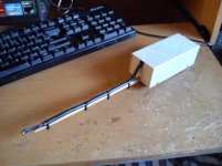
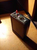
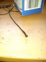
For the sake of experimentation and usefulness, I have made each mic in a different "form factor". Feel free to laugh at them, my friends say they look quite funny
I have recently build 6x microphones as designed by Linkwitz (System Test). I use them to multitrack recording a set of drums. Sound is excellent for the cost of the materials. The problem I get with some of those mics, as when placing one inside the subkick, is that signal clips from time to time the input of my soundcard. It only happens from time to time, say 5 or 6 clips along a 2 minutes recording. I cannot reduce the gain of the opamp because I already potted the pcbs inside the mic enclosures.
Because the voltage swing can be so high, if I reduce it I can record without clipping while the opamp is still able to amplify without clipping itself (it's supplied with +/-9v). So I think I can make an H attenuator using 2x XLR connectors and a piece of cable, and fitting the resistor network inside the plug. I will place the attenuator in the receiving end, so to avoid driving long cables after it. Anyway, they are driving something like 5 meters of balanced cable, so it's not a huge distance.
The microphones are selfpowered with 2x 9v batteries each one. Output is balanced, with a 200 ohm resistor on both hot and cold outputs, as seen in the circuit. The input of the next stage is balanced, a Tascam soundcard stated as 15K in the specs sheet.
So if I am using this calculator corrently (Passive Audio Attenuators), assuming a 10 ratio of input/output impedance would yield to:
-Input impedance of attenuator: 2000ohm (ten times 200ohm output impedance)
-Output impedance of attenuator: 1500ohm (1/10th of 15000ohm)
-Attenuation required (1-40): 10dB
So the results are shown in the attached picture. Do I have made all the calculations properly?
I am thinking too in fitting a pot in the microphone instead of a fixed attenuator, but due to all the disadvantages of a pot and not needing to "dial in" a precise amount of attenuation, I think I will go with an fixed H pad.
For the sake of experimentation and usefulness, I have made each mic in a different "form factor". Feel free to laugh at them, my friends say they look quite funny
Attachments
Last edited:
Oh, and as with all balanced connections, I suppose it would be preferable to use 1% resistors, or even as matched as possible, right?
Hi, the XLR "appears" to be only balanced as far as impedance goes. There is no signal going to Pin 3. I don't know why he didn't make use of the other OpAmp & design it as properly balanced ? In future i would ! Sure 1% resistors or better !
I think this could achieve what you want.
I think this could achieve what you want.
Attachments
Yeah, I don't know why not use the second part of the opamp. From what I know impedance balancing get most of the job done, but it would cost only 3 or 4 more resistors to do it that way.Hi, the XLR "appears" to be only balanced as far as impedance goes. There is no signal going to Pin 3. I don't know why he didn't make use of the other OpAmp & design it as properly balanced ? In future i would ! Sure 1% resistors or better !
I think this could achieve what you want.
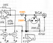
So let me get it, should I match both 200ohm resistors right? I have used 220 because that's what I had at hand. So I can add another 220ohm in series with the hot output (having hence 440ohm) and another 220ohm from this resistor's output to ground.
Then I would have a balanced output impedance of 220ohms and a reduction in signal of 2/3rds, right?
Thanks Zero D!
Yeah, 2 x 220R in series with the Hot output = 440R instead of 430R won't make any difference you will hear.
Replace BOTH Pin 2 & Pin 3 200R's to Ground with your 220R's.
Let me know how it goes.
Replace BOTH Pin 2 & Pin 3 200R's to Ground with your 220R's.
Let me know how it goes.
Yeah, 2 x 220R in series with the Hot output = 440R instead of 430R won't make any difference you will hear.
Replace BOTH Pin 2 & Pin 3 200R's to Ground with your 220R's.
Let me know how it goes.
I already used 220ohm 1% for those spots, so no need to replace them. I will just make a short cable, with an XLR male on one end and an XLR female on the other end, and in one of them fitting a series 220 resistor and after it, another 220 to ground.
In case I need the attenuation, I will just fit the cable inbetween. Pretty much plug and play

Why did you adopt +10dB of gain for the opamp?
The system noise will be less if you used a higher gain, maybe +20dB, if you can get the bandwidth with your chosen opamp.
40mVac from 100dB SPL and +-9Vdc allows ~ 6Vac.
That would be ~ 140dB.
Is it really the opamp that is voltage clipping?
Or is it a current clipping, or is the electret clipping?
Last edited:
I don't think is current clipping, because of 15k input impedance, maximum voltage swing and being an OPA2134 (can supply *quite a lot* of current). My theory of why it happens is that it is just overloading the interface input, when monitoring the recording peaks go up to -6dB or -3dB without problem, except when it goes higher, then it clips. But it clips because of reaching the 0dBFS, not before. Everything goes well under 0dBFS.Why did you adopt +10dB of gain for the opamp?
The system noise will be less if you used a higher gain, maybe +20dB, if you can get the bandwidth with your chosen opamp.
40mVac from 100dB SPL and +-9Vdc allows ~ 6Vac.
That would be ~ 140dB.
Is it really the opamp that is voltage clipping?
Or is it a current clipping, or is the electret clipping?
If the electret element were clipping, it couldn't go past a predefined point, lets say e.g. -15dB
The point is that noise floor is already low enough, inaudible at least. The problem is that it outputs a too much hot signal, it could has been solved by using 0dB of gain in the opamp, but as I said it has been already potted so the easier way is to build the mic from scratch, or just make an attenuator pad to fit in when necessary. The attenuator would reduce usable signal AND noise in a proportional manner, so SNR would be more or less the same. But as I said, noise floor is not a problem at all. Increasing the opamp gain to +20dB would only make it worse by 10dB 😱The system noise will be less if you used a higher gain, maybe +20dB, if you can get the bandwidth with your chosen opamp.
Oh, and I forgot to answer this. If the opamp were clipping, I would have a visible clipped signal under 0dBFS. But I don't see any clipping before 0dBFS, and at 0dBFS is the audio interface input which is clipping.Is it really the opamp that is voltage clipping
Could it be that BOTH opamp and interface's input clip at the same voltage level? Yeah sure, it could be. But what I am sure is that the opamp doesn't clip before the interface's input.
It looks like you are confirming that the next stage is too sensitive for the maximum signal you are able to send.
Attenuation seems like the only solution.
Attenuation seems like the only solution.
I would like to build another one, this time without gain.
Could tell me if just using a 1k feedback resistor would be ok?
Could tell me if just using a 1k feedback resistor would be ok?
1k feedback will be OK if the signal level does not go too high. The 1k appears as a load to the opamp, in parallel to the main load.
The gain will now be 1+[1/5] = 1.2times (+1.6dB)
The gain will now be 1+[1/5] = 1.2times (+1.6dB)
and what would happen if I were to set it as unity gain by jumpering the feedback resistor? the resistance seen in parallel with the load would be 5k, right?
- Status
- Not open for further replies.
- Home
- Source & Line
- Analog Line Level
- Balanced fixed H attenuator for line level