I previously built an F4 and I really love it.
The other day I was dismantling some old tube gear and I found some input transformers with a CT on the secondary.
They are 5:1 (10k:50K) step up and are potted in nice little metal cans.
This got me thinking about people using transformers as phase splitters in tube gear and I was thinking why not apply the same principle with my F4.
I have already rigged up one transformer between my Aikido and my F4.
With 680mV out of my iPod driving the Aikido I get 17V out of the mono channel F4.
Upon listening it sounds really good so I figured I'd give this a go.
With a full 2V input signal I should be able to put the F4 into clipping on a mono 100W channel.
I did all this testing on my F4 biased at 400mV which is double the specified bias.
I built my power supply to handle the extra load and I'm still holding strong at loaded 21V rails.
My heatsinks are fan cooled and even at 400mV bias my middle pin temperatures are barely touching 60C.
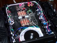
So, my new set of F4 boards showed up today and I have begun the stuffing of those boards.
The other day I was dismantling some old tube gear and I found some input transformers with a CT on the secondary.
They are 5:1 (10k:50K) step up and are potted in nice little metal cans.
This got me thinking about people using transformers as phase splitters in tube gear and I was thinking why not apply the same principle with my F4.
I have already rigged up one transformer between my Aikido and my F4.
With 680mV out of my iPod driving the Aikido I get 17V out of the mono channel F4.
Upon listening it sounds really good so I figured I'd give this a go.
With a full 2V input signal I should be able to put the F4 into clipping on a mono 100W channel.
I did all this testing on my F4 biased at 400mV which is double the specified bias.
I built my power supply to handle the extra load and I'm still holding strong at loaded 21V rails.
My heatsinks are fan cooled and even at 400mV bias my middle pin temperatures are barely touching 60C.
So, my new set of F4 boards showed up today and I have begun the stuffing of those boards.
Attachments
![0530141702[1].jpg](/community/data/attachments/392/392139-8b6b3c4270f0d4e84a882f6c831a9b43.jpg?hash=i2s8QnDw1O)
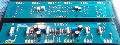
I did something a little different with my F4 boards that I haven't seen any body else do.
There is an extra hole on the 220uF spot so you have flexibility on the diameter.
I took this opportunity to place Vishay MKP1837 polypropylene caps as a bypass on the electrolytic.
NOW, before anybody starts jumping up and down........I have no idea whether it makes any difference at all, but hey that's why it's DIY folks.
Attachments
![0618141806[1].jpg](/community/data/attachments/392/392163-1f967fedbfb1eff5e23fc3500e6932bd.jpg?hash=H5Z_7b-x7_)
Tomorrow I will match the rest of my source resistors and get them stuffed.
I expect to have the two F4's inside this single chassis running standard or maybe a little more than standard bias.
The input transformers will take the input from the RCA and the CT will go to ground with the + on the secondary going to one board and the - of the secondary to the other board.
I think this is a clever idea and I really hope it works out in the end.
I love the idea!
It's amazing how you can take a pair of vintage transformers and make 2 stereo 25WPC amps into one stereo 100WPC amp.
Magnetics are magical. (Or something like that...) 😀 😀 😀
Eagerly awaiting more photos and results.
It's amazing how you can take a pair of vintage transformers and make 2 stereo 25WPC amps into one stereo 100WPC amp.
Magnetics are magical. (Or something like that...) 😀 😀 😀
Eagerly awaiting more photos and results.
that's 10K CT : 50K
which means , as written on it , 2K5+2K5 :50K
if you rotate it , to have CT at output , that's 50K : 2K5+2K5
recalculating to voltage ratio , that's 1:0.22+0.22
disclaimer - morning coffee just arriving
which means , as written on it , 2K5+2K5 :50K
if you rotate it , to have CT at output , that's 50K : 2K5+2K5
recalculating to voltage ratio , that's 1:0.22+0.22
disclaimer - morning coffee just arriving
The print on the side shows a CT on the Primary at 2.5k.
The print does not show the CT on the Secondary.
However, the schematic for the amp it came out of shows the CT on the Secondary and it is there, I verified this with my inductance meter, it's just not printed on the can.
So I will have 10k:25k-0-25K configuration which will be 1:2.5-0-2.5
This should (in theory) give my Aikido the ability to swing +- 36V (minus any losses) into the Balanced F4.
I'll draw a schematic for what I plan and post it later.
re-read #5
voltage ratio is √ of impedance ratio
also , impedance to No. of turns is behaving by square law ....... so :
if we assume that 50K is having CT , that means 50K side is 12K5+12K5
10K : 50K is 1:2.23 [V/V] ......... which is , then , 1:1.11+1.11 [V/V]
voltage ratio is √ of impedance ratio
also , impedance to No. of turns is behaving by square law ....... so :
if we assume that 50K is having CT , that means 50K side is 12K5+12K5
10K : 50K is 1:2.23 [V/V] ......... which is , then , 1:1.11+1.11 [V/V]
Last edited:
Thank You Zen for the clarification.
SO, I get 8V RMS out of the Aikido & 16.7V RMS out at the speaker terminals from a 580mV source (iPod) with the transformer between the Aikido output and F4 input.
I should have plenty of V out with a 2V source to drive the Balanced F4 into clipping???
SO, I get 8V RMS out of the Aikido & 16.7V RMS out at the speaker terminals from a 580mV source (iPod) with the transformer between the Aikido output and F4 input.
I should have plenty of V out with a 2V source to drive the Balanced F4 into clipping???
if Aikido is capable to receive 2V input , then yes
or , better to go backwards :
balanced F4 will produce , say , 80Vpp at output
then you need 80V/(2x 1.11) at xformer input
that's roughly 36Vpp
divide with (2 x √2) , that's 12.74Vrms
btw. I'm always thinking in pp terms , translating to RMS only when speaking about Watts
or , better to go backwards :
balanced F4 will produce , say , 80Vpp at output
then you need 80V/(2x 1.11) at xformer input
that's roughly 36Vpp
divide with (2 x √2) , that's 12.74Vrms
btw. I'm always thinking in pp terms , translating to RMS only when speaking about Watts
Last edited:
My Aikido will happily accept 2V input, it spends its life attached to a 2V source with near max volume since my speakers are 81db. 25W is a little weak for my new room on those speakers but at max volume it puts out a "house cleaning loud" level.
From my calculation I have about 10db of gain from 580mV to 2V. It will take 4.5db of gain to get to 100W from the 34W I can get out of my single mono F4. I should have about 5db or so to spare.
This will make for a pretty flexible application with a little extra gain headroom for 1 and 1.5V sources.
This may just work out perfectly.
Last edited:
So, I used the test file burned to a CD from THIS thread about how much power you really need.
It's a 220Hz test tone at -12db reference level.
My CD player with this test tone drives my F4 without the transformer attached to 18.23V RMS at the speaker terminals, which puts my F4 into clipping.
With the transformer in place I should have around 52V P-P, I may look at dropping some gain in my Aikido if needed.
in final setup , sweep it (1W,dummy load) to see does xformer need any additional (EQ) loading for linearisation
From the single channel tests I ran a few weeks ago I didn't notice any need for EQ with a 20-20K sweep @ 35W.
But I will definitely check this out once it's all said and done.
But I will definitely check this out once it's all said and done.
we are very patientFunny FE will be more suited to the task…😀😀😀😀
if i ever finish it.

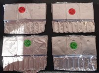
Boards Finished
Here I have the boards finished, I will probably order my FET's next week.
Just FYI, I use Cardas Quad Eutectic solder.
I don't subscribe to the Audiophile hype about the stuff but I do know it's the nicest solder I have ever worked with.
It's a really reasonable price if you order it from Percy Audio.
Attachments
also see
http://www.diyaudio.com/forums/pass-labs/188109-introducing-magma-front-end-ba-2-f4.html
and
http://www.diyaudio.com/forums/pass-labs/97540-f4-power-amplifier-341.html
post 3407 and following
best
Bob
http://www.diyaudio.com/forums/pass-labs/188109-introducing-magma-front-end-ba-2-f4.html
and
http://www.diyaudio.com/forums/pass-labs/97540-f4-power-amplifier-341.html
post 3407 and following
best
Bob
I remember reading through those posts a long time ago once 6L6 turned me on to the F4 to pair with my Aikido.
Thank You, I ended up ordering my FET's from Alweit this time around too.
My first set are so closely matched that my temperature difference across all 12 FET's is only 3C.
I'm really impressed by his matching ability, but when you buy whole boxes and match them I guess you have a leg up on us guys that order a sleeve or two and hope for the same result.
- Status
- Not open for further replies.
- Home
- Amplifiers
- Pass Labs
- Balanced F4 With Input Transformer