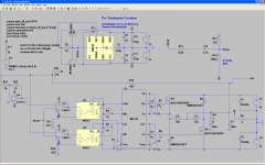
I wipped this together today based on the crown BCA topology: http://i.imgur.com/4vZAmSu.png?1
Has anyone ever seen a single ended version like this ? I have not apart from in a "interleaved PWM" patent.
switching frequency in my simulation is around 540kHz.
Has anyone ever seen a single ended version like this ? I have not apart from in a "interleaved PWM" patent.
switching frequency in my simulation is around 540kHz.
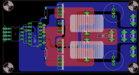
I spent the day cadding a board for a little baby version of a Crown K1 output module.
Why am i doing this you may ask ? Well i like exploring things and the BCA topology has been staring me in the eye for some time now.
This module will be using two IRFP540 mosfets and two MUR1560 diodes as well as two CoilCraft ED0006-AL inductors.
The optocoupled input is a HCPL2231, just like in the actual Crown design although they used a TLP2601/HCPL2611.
I chose the HCPL2231 as i do not have the ones originally used as eagle libraries.
The modulator board however will probably be something of my own design.
Attachments
Tekko,
Nice design! Can this be made to operate as a transconductance amp (voltage to current amp)? I am looking for a way to get the sound and behavior of the Pass F1 in a class D.
Nice design! Can this be made to operate as a transconductance amp (voltage to current amp)? I am looking for a way to get the sound and behavior of the Pass F1 in a class D.
You can always make an amp into a transconductance amp by using a current feedback loop around the whole thing. Depending on the amp topology it might get tricky to ge the thing stable sometimes however.
Regards
Charles
Regards
Charles
You can always make an amp into a transconductance amp by using a current feedback loop around the whole thing. Depending on the amp topology it might get tricky to ge the thing stable sometimes however.
Regards
Charles
The F1 achieves this without feedback. Is it possible to make a class D do this?
FIRST WATT F1
Hello,
I 've studied how Crown controls the bias current through the coils L1 and L2: They have shunt resistors in series to both coils and by controlling overlap, the current is clearly defined as: Average voltage (a function of overlap) divided by shunt resistor value. Very clever! Since you don't have those resistors, you should find a way to regulate / control bias current otherwise you risk a runaway situation.
BTW: I found some errors on the Crown K1 and K2 schematics that can be downloaded on their website.
So in addition they have a thermally dependent resistor pick up the heatsink temperature and reduce overlap when the unit gets hotter.
I have identified one of the errors in their schematic, in the control circuit schematic, one of the output inductors are wired to -Vcc rather than the mosfet/diode junction.
Note that this is a WIP, the overlap adjustment on the BCA topology is in a way very similar to the quiescent current adjust on a class AB amp.
The shunt resistors and the thermistor has nothing to do with the overlap adjust, there is no connection what so ever, the shunt resistors connect to nothing but two comparators that shuts off the gate drive during an overload condition, the current monitor does connect to the triangular wave generator but as its only sensing the speaker output it has no part in the overlap control either, the overlap control is solely the pot on the output modules and nothing else and some speaker output DC offset feedback.
"The shunt resistors and the thermistor has nothing to do with the overlap adjust, there is no connection what so ever"
The shunt resistors are for overcurrent comparator, right, but they are ALSO needed to keep bias current steady. With no shunts and ideal (0-Ohmic) coils, even the smallest overlap would result in runaway current.
"I have identified one of the errors in their schematic, in the control circuit schematic, one of the output inductors are wired to -Vcc rather than the mosfet/diode junction."
Right, the second error is a shorted input compressor Opto-resistor.
This is similar to the two transistor forward/flyback topology adapted to class D power amplifier. Interesting approach. I wonder what happens with delta bigger than .5. Doesn´t inductors saturate?
The secret is to choose inductors with a current rating exceeding the max the amp will ever produce, crown uses 40A rated inductors and they do not spec what core material is used.
I will use the ones coilcraft has for the zetex class d as im just building a small ~100W into 4 ohm version.
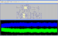
I added the shunt resistors: http://i.imgur.com/3F6bUen.png
I was indeed unable to get a steady overlap without them, now thats prolly more average current than crown runs, but simulation does not show the things mentioned in the manual for the overlap adjust.
I will use the ones coilcraft has for the zetex class d as im just building a small ~100W into 4 ohm version.
I added the shunt resistors: http://i.imgur.com/3F6bUen.png
I was indeed unable to get a steady overlap without them, now thats prolly more average current than crown runs, but simulation does not show the things mentioned in the manual for the overlap adjust.
Attachments
No, the inductor doesn't saturate because of current, although you put an inductor rated to 1000A, it also will saturate if the reset volts*second is lower than the set one, and the core accumulates magnetic energy without release it.
I personally believe the inductor will saturate at largest audio signals as it will not discharge magnetic energy between PWM cycles.
I personally believe the inductor will saturate at largest audio signals as it will not discharge magnetic energy between PWM cycles.
Last edited:
"it also will saturate if the reset volts*second is lower than the set one"
exactly that is what I mean. Overlap means less time for magnetic re-set, so the current will rise forever with ideal coils an no resistors - or rise only as far as the resistor voltage is equal to the applied average DC voltage if the shunts are in.
exactly that is what I mean. Overlap means less time for magnetic re-set, so the current will rise forever with ideal coils an no resistors - or rise only as far as the resistor voltage is equal to the applied average DC voltage if the shunts are in.

- Status
- Not open for further replies.
- Home
- Amplifiers
- Class D
- Balanced current interleaved PWM class d output stage