This thread is for "How to build a Balanced B1 Korg Triode" preamplifier.
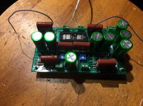
First, the hardware, I purchased two sets of PCB w/FETS and Korg Triode tubes from the diystore. Boards were stuffed the parts from the BOM with Nichicon UES 1000uF filter caps and Panasonic 10uF film caps (these were the extras I mistakenly bought while building a BZLS).
Once both boards were stuffed and the test voltages confirmed for both boards, I marked one board for Left + and Left -. With the other board marked Right + and Right -.
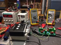
I measured each side of each board using REW software, Akitika 1K generator and a Behringer UM2 sound card, for 1.5% 2H negative, 1% 2H negative, null point of 2H, 1% 2H positive and 1,5% 2H positive. Here are the results:
R+ R- L+ L-
1.5% 8.57 vdc 8.61 vdc 8.84 vdc 9.51 vdc
positive 2H
1% positive 9.53 vdc 9.52 vdc 9.41 vdc 10.53 vdc
Null 2H 11.62 vdc 11.43 vdc 11.41 vdc 11.57 vdc
0.043%
1% 12.44 vdc 12.12 vdc 12.30 vdc 12.30 vdc
negative 2H
1.5% 13.07 vdc 12.50 vdc 12.84 vdc 12.70 vdc
negative 2H
This is the same procedure I used for my B1 Korg Triode preamp, the hard part was adjusting each channel in balanced mode.
First, the hardware, I purchased two sets of PCB w/FETS and Korg Triode tubes from the diystore. Boards were stuffed the parts from the BOM with Nichicon UES 1000uF filter caps and Panasonic 10uF film caps (these were the extras I mistakenly bought while building a BZLS).
Once both boards were stuffed and the test voltages confirmed for both boards, I marked one board for Left + and Left -. With the other board marked Right + and Right -.
I measured each side of each board using REW software, Akitika 1K generator and a Behringer UM2 sound card, for 1.5% 2H negative, 1% 2H negative, null point of 2H, 1% 2H positive and 1,5% 2H positive. Here are the results:
R+ R- L+ L-
1.5% 8.57 vdc 8.61 vdc 8.84 vdc 9.51 vdc
positive 2H
1% positive 9.53 vdc 9.52 vdc 9.41 vdc 10.53 vdc
Null 2H 11.62 vdc 11.43 vdc 11.41 vdc 11.57 vdc
0.043%
1% 12.44 vdc 12.12 vdc 12.30 vdc 12.30 vdc
negative 2H
1.5% 13.07 vdc 12.50 vdc 12.84 vdc 12.70 vdc
negative 2H
This is the same procedure I used for my B1 Korg Triode preamp, the hard part was adjusting each channel in balanced mode.
Attachments
Next, I had read the B1 with Korg Triode thread twice and made notes regarding adjustments:
"Ideally then you want to measure the distortion to get it just right. For
distortion this high, it is not that difficult. If you have any sort of decent
sound card on your computer you can use one of the several analyzer
programs to measure the distortion.
Assuming that you can get a numerical figure, start with a high Plate
voltage (pot counter-clockwise), and decrease the voltage until the
distortion is at a minimum, where the 2nd harmonic is being cancelled
and you have 3rd harmonic.
From there you can increase or decrease the Plate voltage until you
reach the distortion number and phase you want.
Keep in mind that the circuit inverts absolute phase. What is "positive
phase" 2nd harmonic at the output of the circuit will become negative
phase when you again reverse the phase at the output, typically at the
speaker connection, in order to have correct absolute phase."
"If you have a means of measuring distortion but can't tell the phase
(for example, using a soundcard to make the measurement) then simply
find the lowest distortion point, and then as you turn the pot clockwise
you go into positive phase, or negative phase with counterclockwise."
"
To the extent the balanced channels are matched, they will cancel, leaving
5th. You can unbalance the 2nd harmonic if you like - the channels are
adjustable as described in the article. You could set one side at negative
phase and the other at positive, or simply make them unequal in
amplitude but not phase"
After re-reading these quotes from NP, I sent him an email for help:
1st reply:
Depends on what you want. If you want to null the 2nd harmonic out,
then you would set the 2 channels identically.
If you want more 2nd, then you would set them differently, for example:
Keeping mind that the individual channels are inverting, if you have a
+ incoming signal it becomes the - outgoing signal and vice versa.
+ in to L ch = -out
- in to R ch = +out
adjusting L ch for more positive phase 2nd gives more negative phase 2nd in balanced out.
(less negative phase 2nd is same as more positive result)
adjusting R ch for more negative phase 2nd gives more negative phase 2nd in balanced out.
(less positive phase 2nd is same as more negative result)
I hope that's clear enough.....
After several hours of adjusting the Left channel in Balanced mode, I sent him my results and his reply:
"Looks to me like you have a good handle on it."
This is what I needed to devote more hours to adjusting the pc boards.
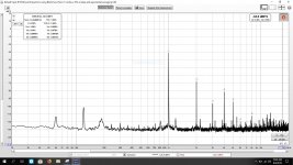
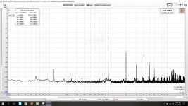
Here are the REW printouts of the final adjustments for the Left and Right channels:
"Ideally then you want to measure the distortion to get it just right. For
distortion this high, it is not that difficult. If you have any sort of decent
sound card on your computer you can use one of the several analyzer
programs to measure the distortion.
Assuming that you can get a numerical figure, start with a high Plate
voltage (pot counter-clockwise), and decrease the voltage until the
distortion is at a minimum, where the 2nd harmonic is being cancelled
and you have 3rd harmonic.
From there you can increase or decrease the Plate voltage until you
reach the distortion number and phase you want.
Keep in mind that the circuit inverts absolute phase. What is "positive
phase" 2nd harmonic at the output of the circuit will become negative
phase when you again reverse the phase at the output, typically at the
speaker connection, in order to have correct absolute phase."
"If you have a means of measuring distortion but can't tell the phase
(for example, using a soundcard to make the measurement) then simply
find the lowest distortion point, and then as you turn the pot clockwise
you go into positive phase, or negative phase with counterclockwise."
"
To the extent the balanced channels are matched, they will cancel, leaving
5th. You can unbalance the 2nd harmonic if you like - the channels are
adjustable as described in the article. You could set one side at negative
phase and the other at positive, or simply make them unequal in
amplitude but not phase"
After re-reading these quotes from NP, I sent him an email for help:
1st reply:
Depends on what you want. If you want to null the 2nd harmonic out,
then you would set the 2 channels identically.
If you want more 2nd, then you would set them differently, for example:
Keeping mind that the individual channels are inverting, if you have a
+ incoming signal it becomes the - outgoing signal and vice versa.
+ in to L ch = -out
- in to R ch = +out
adjusting L ch for more positive phase 2nd gives more negative phase 2nd in balanced out.
(less negative phase 2nd is same as more positive result)
adjusting R ch for more negative phase 2nd gives more negative phase 2nd in balanced out.
(less positive phase 2nd is same as more negative result)
I hope that's clear enough.....
After several hours of adjusting the Left channel in Balanced mode, I sent him my results and his reply:
"Looks to me like you have a good handle on it."
This is what I needed to devote more hours to adjusting the pc boards.
Here are the REW printouts of the final adjustments for the Left and Right channels:
Attachments
How I was able to measure the combined Balanced 2H measurement:
With the help of xrk971 and Mark Johnson, I wired a TRS and female XLR connector as follows:
XLR: Pin 1 = ground: pin 2 = positive; pin 3 = negative. Tip to pin2 of the XLR, ring to pin3 of the XLR with the sleeve and pin 1 of the XLR with no connection.
This gave me the connection needed from the pc board to the sound card.
With the pc board powered by my lab supply at 24 vdc, the Akitika was adjusted so that 1v rms was measured at the output of each side of the pc board. The XLR adapter cable was plugged into the sound card and the male XLR connector which was wired to the pc board outputs.
With my laptop running on batteries, the REW software was launched, first adjustments were made to achieve 1.5% 2H. Since both pots on each pc board are adjusted, I concentrated on reducing 3H while still measuring 1.5% 2H. Adjusting each board for 1.5% 2H is very easy, reducing 3H to an almost null point requires constant back and forth between the two pots, adding/subtracting 2H all the time staying with 1.5% 2H.
Every time I thought I had good results, I would record the REW screen with the L+, L-, R+, R- voltage adjustments. I would name the screen shot file with the voltage adjustments.
After I was happy with the results of each adjustment, I would power every thing down and retest the next day to verify I could duplicate the results.
With the final adjustments for each channel verifed, I removed the XLR connectors from each pc board, and measured each L+, L-, R+, R- individually to see where each side of the pc board adjustment gave for distortion results. The following graphs file names are the results:
Attachments
-
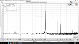 Left channel balanced - = 10.53vdc 1.5% final adjust.JPG180.1 KB · Views: 1,330
 -
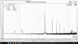 Left channel balanced + = 9.22vdc 1.5%.JPG final adjust.JPG180.6 KB · Views: 194
 -
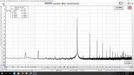 Right balanced R- = 9.55 vdc final adjustment.JPG181.6 KB · Views: 179
 -
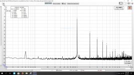 Right balanced R+ = 10.52 vdc final adjustment.JPG181.2 KB · Views: 169
In conclusion: I would like to thank xrk971 for teaching me how to measure distortion levels using an affordable method, Mark Johnson for not giving me easy answers and making me think.
Of course, NP for the design of the B1 Korg Triode, and the incentive and road map for the "how to" part.
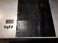
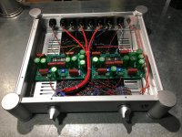
For vibration control, I have 3mm rubber mounts for each pc board, with 3M automotive vibration mat for the top and bottom chassis panels, and 2mm thick memory foam for under the Korg tube.
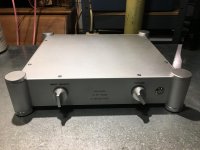
I think I'll take a break and tomorrow start on the chassis using an ALPS shorting type 3 position 4 pole selector switch (thanks Zen Mod), and a 24 step quad 50K log volume control. I found a nice chassis to build it in and knobs which look just like the knobs on Threshold FET 9 & 10 preamps.
Of course, NP for the design of the B1 Korg Triode, and the incentive and road map for the "how to" part.
For vibration control, I have 3mm rubber mounts for each pc board, with 3M automotive vibration mat for the top and bottom chassis panels, and 2mm thick memory foam for under the Korg tube.
I think I'll take a break and tomorrow start on the chassis using an ALPS shorting type 3 position 4 pole selector switch (thanks Zen Mod), and a 24 step quad 50K log volume control. I found a nice chassis to build it in and knobs which look just like the knobs on Threshold FET 9 & 10 preamps.
Attachments

My final adjustments for 1.5% negative 2H from both channels. Left channel is adjusted for 1.5% positive 2H, and the right for 1.5% negative 2H.
I have a terminal strip for 6 with 2 grounds for the T7-T8 connections, this way I can easily hook up a DVM and make changes.
I'm very curious as to how it will sound with 1.5% negative 2H on one channel and 1.5% positive 2H on the other channel. With all the measurements I've recorded for each side of both channels, all I will need to do in the future is adjust the plate voltage to the desired feedback amount, including null of 2H.
I plan on using this preamp with the F5T v3 balanced mono blocks I'm building.
Attachments

Just to clarify, in order to get 1.5% positive and 1.5% negative out of the preamp, both channels will require adjustments for 1.5% negative as the Left channel will invert in balanced mode.
Excuce me, 1.5% POSITIVE adjustment for both channels. In the future I should refer to the adjustments as "above 11 vdc, and below 11 vdc" to keep me from getting confused.
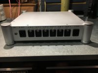
I finally finished my Balanced B1 Korg preamp, rainy day made the difference. I gave up marking the PC boards Left and Right, now they are marked + for positive 2H and - for negative 2H. This way I can change the boards from right and left if I want positive 2H or negative 2H. Far to many double negatives for me to keep track of.
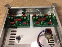
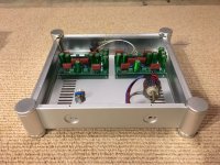
I used a 6 position solder strip, grounds on the ends and then the four test positions to measure plate voltage for the two PC boards. A 3 position 4 pole selector switch, make before break with 1 M ohm resistors from L+,R+ and L- R- to ground on the inputs, A nice trick from NP to reduce noise while selecting inputs. Twisted pairs with a shield for input wiring.
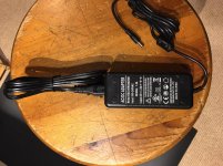
I had a scare when I first powered it up, after completing all the internal wiring, the on-off switch LED was slowly flashing and the Korg Nutube did not have the cathodes glowing. The $10 wall wart, which works perfectly with the regular B1 Kord triode preamp, does not work with the Balanced version. My lab power supply powers it up along with the Meanwell power supply from an ACA v1.6 amplifier.
I'm using the preamp with the ACA mono blocks in balanced mode with my Threshold FET 10Pe phono section, it has balanced outputs and the Music Hall 25.3 DAC, which also has balanced outputs.
I have to admit, the Balanced Zen line stage is a better match for the ACA's. I built this preamp for the F5T v3 mono blocks I'm building.
I used a 6 position solder strip, grounds on the ends and then the four test positions to measure plate voltage for the two PC boards. A 3 position 4 pole selector switch, make before break with 1 M ohm resistors from L+,R+ and L- R- to ground on the inputs, A nice trick from NP to reduce noise while selecting inputs. Twisted pairs with a shield for input wiring.
I had a scare when I first powered it up, after completing all the internal wiring, the on-off switch LED was slowly flashing and the Korg Nutube did not have the cathodes glowing. The $10 wall wart, which works perfectly with the regular B1 Kord triode preamp, does not work with the Balanced version. My lab power supply powers it up along with the Meanwell power supply from an ACA v1.6 amplifier.
I'm using the preamp with the ACA mono blocks in balanced mode with my Threshold FET 10Pe phono section, it has balanced outputs and the Music Hall 25.3 DAC, which also has balanced outputs.
I have to admit, the Balanced Zen line stage is a better match for the ACA's. I built this preamp for the F5T v3 mono blocks I'm building.
Attachments
Just so that I understand after inversion you have a positive H2 in both Left and Right channels?
nash
nash
"To the extent the balanced channels are matched, they will cancel, leaving
5th. You can unbalance the 2nd harmonic if you like - the channels are
adjustable as described in the article. You could set one side at negative
phase and the other at positive, or simply make them unequal in
amplitude but not phase"
I adjusted so that they are unequal in amplitude but equal in phase, this adjustment provided the lowest 3H for each channel.
"If you want more 2nd, then you would set them differently, for example:
Keeping mind that the individual channels are inverting, if you have a
+ incoming signal it becomes the - outgoing signal and vice versa.
+ in to L ch = -out
- in to R ch = +out"
Which is how the boards are installed. Once the F5T amps are finished, I plan on changing the R channel to positive and with the inversion, negative 2H on both channels.
I'm curious as to what the sound will be with one channel positive and one channel negative. Since I have recorded all the measurements, all I will need to do is set each side to the plate voltage from previous measurements. I can set them to either negative 2H on both channels or positive 2H on both channels.
Since this is a balanced setup each channel input signal has a +phase and a - phase.
The procedure you outlined shows that you matched overall the Left channel and the Right channel spectrum. Does this imply that you matched the Right + to the same spectra as the Left +? And similarly the Right- and the Left -?
Not sure of your exact procedure but in setting up my BA3bal I treated each phase as a separate channel so that all 4 phases have the same spectra.
nash
When I was making the adjustments, I adjusted R+ and R- together along with L+ and L-. First, I made a rough adjustment for 1.5% 2H on either R+ or R-, then I would go back and forth adjusting R+ and R- so that I would have the 1.5% 2H and 3H decreasing. It is easy to adjust for 2H, however, 3H amounts will increase at times. The adjustments required me to wait 30 seconds for the results to stabilize, if I saw 2H rising above the 1.5% or 3H increasing, I would back off the previous adjustment.
When I would find the sweet spot of 1.5% 2H and 3H to the lowest level, I recorded the plate voltage for each L+, L-and R+, R-.
It took me about 1 - 1.5 hours for each channel, for each 2H level I chose. Since I recorded each channel for 1%, 1.5% positive and negative phase and the 2H null point, I tested each channel by un-adjusting each pot, and then setting each adjustment to the values I recorded. I was very concerned with being able to duplicate the adjustments each day I worked on them. At times I thought it would be nice to be able to see positive 2H and negative 2H, the REW software just gives 2H amplitude, not phase. However, knowing the plate voltage for the 2H null point, then when adjusting lower plate voltage was positive 2H and increasing plate voltage gave negative 2H.
It took me 4 days of work to make and record all the adjustments, patience making the adjustments made all the difference. It reminded me of adjusting multiple carburetors on an engine, set idle speed, then mixture and readjust idle speed, repeat, etc.
Once I was able to find the settings for each channel where 3H would decrease, and 2H stabilized, it was a very rewarding feeling. I had so much fun with this project, it got me away from the drill press drilling holes endlessly for my F5T amps, now that it is done, it's back to drilling more holes.
Yes the pots can be fiddly tiresome and repeatability is not that great.
If you can, try setting each phase separately, essentially treating as 4 separate channels matched identically. The individual and the balanced work out differently.
Hope you find a setting that you are happier with.
nash
If you can, try setting each phase separately, essentially treating as 4 separate channels matched identically. The individual and the balanced work out differently.
Hope you find a setting that you are happier with.
nash
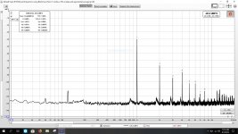
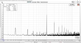
Here are the final adjustments which provides 1.5% positive 2H on both channels. Notice the variations in plate voltage for each channel, Korg Nutube production variances? Each channel has 3H at the lowest level I could adjust to and keep noise and 4H to low levels.
With the speaker connections swapped, the final result is 1.5% 2H negative phase.
With the speaker connections swapped, the final result is 1.5% 2H negative phase.
Attachments


- Home
- Amplifiers
- Pass Labs
- Balanced B1 with Korg Triode