Hallo all,
I am Still pursueing the differential input and bridged (differential out) power amplifier.
My main concern is how to couple the halfs together.
Do they need to be closely coupled, via feedback, or can i just make 2 (nearly) identical power amps and feed the differential signal to it ?
Your opinions please !
best regards
Simon
Those are two separate issues, input and output.
A balanced input can be realized by any op amp, or the discrete equivalent of that if you prefer.
A differential or bridged output is cam be realized using two amplifiers, one driven by the inverted output of the other. There are different ways to derive the inverted signal, from using an inverting op amp to using the negative feedback input of the second amp for input. If you are not familiar with these techniques, you need to do some homework -- here are some websites with more information.
Elliot Sound Products has a nice tutorial on this:
http://sound.westhost.com/project20.htm
http://sound.westhost.com/project20.htm
On the Hafler technical support site, there is a discrete op amp design for inverting the signal, and an example of using the negative feedback input. The op amp appears to be a Borbely design. Unfortunately, I think there is an error in the DH-202 schematic. The input is connected to the output, likely a drafting error. At any rate, here it is:
http://www.hafler.com/techsupport/pdf/DH-202_PC-7_bridgeKitForDH-200.pdf
http://www.hafler.com/techsupport/pdf/DH-222_bridgeKitForDH-220.pdf
Simon, Have you been following the various aleph-X threads ?
This amplifier has differential input and output with the feedback loop (partly) making the error signal common mode. To me, this seems like a much more elegant solution than the more typical bridge arrangement where each half has it's own independant feedback loop.
Dave (also playing with a differential power output stage)
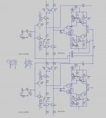
Seems like you are already taking feedback from both sides of the load to each half ! As I understand it this should cause errors to show up as common mode 🙂 🙂
Can I ask :
[1] what is CMRR (with repect to the input) of this circuit like ? Does the output follow the common mode input signal ?
[2] why did you not use a common (to both halves) LTP input circuitry ?
Thanks for sharing you design 😀
Dave
Can I ask :
[1] what is CMRR (with repect to the input) of this circuit like ? Does the output follow the common mode input signal ?
[2] why did you not use a common (to both halves) LTP input circuitry ?
Thanks for sharing you design 😀
Dave
[1] what is CMRR (with repect to the input) of this circuit like ? Does the output follow the common mode input signal ?
Dont know yet 😀
If you got a hint to find out ..................
Please let me know !
[2] why did you not use a common (to both halves) LTP input circuitry ?
I have used LTP's.
1. 1 single ltp
2. a so called symmetrical
1. is nicely working in my simulator , curent feedback, but DC-offset is a bit of a pain and i do not like the way the feedback works. I tapped it rigt into the LTP leg again.
2. has voltage feedback and cannot get it to work wrt to DC-offset servo
Thanks for sharing you design
All of it comes from the web 😀
http://nov55.com/amr/amf1.htm
http://home.swipnet.se/~w-50719/hifi/qrv06/index.html
Simon
Forgot this
I want to feedback amp 1 to amp 2 and vice versa.
It is almost impossible to get 2 identical amps so i need some kine od feedback from one to the other !
grtz
Simon
I want to feedback amp 1 to amp 2 and vice versa.
It is almost impossible to get 2 identical amps so i need some kine od feedback from one to the other !
grtz
Simon
CMRR and Feedback
If some knows how to calculate the CMRR for the above circuit, please let me know !
And if some one has a better scheme on feeding back amp 1 to amp 2 and vice versa, also...............please let me know !
best regards,
Simon
If some knows how to calculate the CMRR for the above circuit, please let me know !
And if some one has a better scheme on feeding back amp 1 to amp 2 and vice versa, also...............please let me know !
best regards,
Simon
bridge adaptor kit
hi
use the bridge adaptor from electronics australia very easy few
easy to get components works bye
thanking you
andrew lebon
hi
use the bridge adaptor from electronics australia very easy few
easy to get components works bye
thanking you
andrew lebon
- Status
- Not open for further replies.
- Home
- Amplifiers
- Solid State
- balanced and bridged amp question