Attachments
Neat circuit!
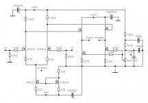
Very unexperienced in SS amp design, but this topology looks very similar to my tube amp -- atleast before i decided to integrate the speaker XO in it. DC-coupling, long-tailed pairs with CCS, no loop feedback, very nice.
However, output DC should controlled frequently (the 5k pot) 🙂
If i'd not be completely entangled with my tube projects, i'd like to try it just to find out how it sounds.
Balanced Mosfet
I built some very simular with a Jet-Mosfet (toshiba-zetex) cascode front end. Then a IR610 follower and IR150 for the output
All current souces are Mosfets. Biased at 2.5 Amps in each leg.You really neeed to do offset at front end. You have to adjust the output cuurent sources have to move quite a bit to change offset. I have all the Fets matched and want the transconductance all thermal to match for lowest distortion and offset-temperature drift. I have Mosfet follows for all supplies and you only need one supply for the output stage. No coupling caps, servos, bipolars. Constant load on the supplies. This about the best Mosfet topology I have heard yet. No source resistors on output. Very stable since it has no global feedback. Excellent dynamic contrast, pitch stability, and resolution. Lot of tube attributes without the hassel other than the heat. A nice elegant easy to build and debug design. I really like haveing the filter caps out of the signal path! You could always put a tube front end on it........
H.H.
Harry:
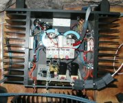
Are those heatsinks painted black? They look like the wakefield extrusion I used on my A75. 6209 I think. You can view my A75 at passdiy. Its in the gallery.
Are those heatsinks painted black? They look like the wakefield extrusion I used on my A75. 6209 I think. You can view my A75 at passdiy. Its in the gallery.
Paint it Black
Yep Just like the Stones song........ Wish I had some more of them.
I will look for your amp and maybe post some close ups of the space heater.
H.H.
Yep Just like the Stones song........ Wish I had some more of them.
I will look for your amp and maybe post some close ups of the space heater.
H.H.
Live and let Die
They're expensive aren't they? I ordered some 12" extrusions once for a telecom product and the truck pulled up with 12' extrusions. Ater I stoped laughing I called the vendor and swore at him untill I started laughing all over again.
The Chassis is from a White audio labs amp. I think Randy borrowed more the the idea for the heatsinks from you. I recently read that Screaming Jay Hawkins fathered possibly 75 children.
I wondered how many unathorized commercial versions of your amp designs you have sired unintentionally? Seems I remeber this current feedback output stage in ..........
H.H.
...And I remember helping Nelson amortize the cost of the original die for that extrusion...in the guise of two Threshold S-500s.
Still have them, in fact.
Grey
Still have them, in fact.
Grey
...nearly
Harry,
I thought the circuit looked familiar (but then once you've seen one diff amps and a pair of source followers etc..)
I've been kicking this topology around for a long time and intend to build it to drive my Quad ESLs which need a maximum 30Vpeak voltage and a 6A peak current delivery (by measurements I made driving them with a class B amp). The circuit you link to was drawn up by Hans Wilson after we exchanged ideas by e-mail. I'm a little further forward in that I've been simulating it and feel pretty confident now that it's ready to build (don't hold your breath though).
Some comments - the linearity of the output stage is determined by how much bias current you run and the load impedance. I now have the source follower loads configured to vary depending on the output current demand in a manner analogous to the Pass aleph designs (though implemented in a different way) and this simulates very well so I can use 3A bias current per side for my 6A peak output requirement (much better than having to burn 6A per side). The balanced nature means a low supply voltage for the output stage and you can use lower voltage, higher transconductance power FETs.
The linearity of the diff. pair stage depends on how much of the possible voltage excursion you want to use. The ciruit posted has a 40V maximum compared to the follower 30V max (excluding losses) which is 3/4 of the way to hard limiting in the diff pair. I will use a maximum possible swing of ~70V meaning that the 30V maximum output is only 3/7 of the way to limiting the diff pair (this can be tuned in simulation so that distortion from the diff pair is at least 10dB below the output stage).
The downside of this is that you cannot ground reference the inputs and ac coupling for the inputs is required. The output stage drains are, actually, grounded and the supply to the follower current sources is -40V on the assumption that the current sources isolate the output from supply ripple better than the follower drain-source would isolate the output from positive supply ripple.
Regards
13DoW
Balance mosfet
Ah........ a true mosfet disciple.
1. I use JFET diff pair/ small signal mosfet cascode voltage gain stage, followed by IRF510 souce followers, driving IRF150 output stage. The amp is DC coupled with no servo and has low offset drift. Thermal coupling between the balanced halves of the circuit is essential for DC coupling.
2. I use a Mosfet follwer with no feedback for a single 30V rail. Both outputs sit about 15 volts above groung but very close each other. I use IRF 150 as current sources with no feedback except 1 ohm source degeneration. The output is bias at 2.5 amps per leg.
3. I have modeled a dynamic curent souce load that is in parallel with a static current source. This keeps the follower on the side of the bridge that is sinking current for turning off and keeps the follower's output impedeance low during large current swings. You can do the feedback for the dynamic current sinks with something like the aleph 3 topoloogy minus the dynamic current sources and with the second voltage gain stage on each leg of course. You don't need a lot of loop feed back to do it is 5 DC coupled mosfets to do the dynamic current sink. Have not built it yet but it models like a dream and the feedback is around the output stage only and uses a moderate amount of NFB.
4. Oh ya........I forgot, it sounds real good.
- Status
- Not open for further replies.
- Home
- Amplifiers
- Solid State
- Balanced amp