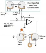
Hi all! I am thinking of using a blender circuit instead of a 3 way switch for a Telecaster with 2 passive coils. I know the usual "Blender" circuit will not suffice. I have a dual gang center detent 500K pot. I want the following gains at these pot positions:
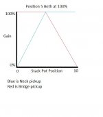
Gain% Neck/Bridge Pot position
0% N / 100% B (0 position)
100% N / 100% B (5 position)
100% N / 0% B (10 position)
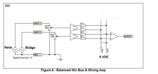
Is this doable without adding a large circuit and battery? Would the circuit that I have attached work?
Thanks for any help
Gain% Neck/Bridge Pot position
0% N / 100% B (0 position)
100% N / 100% B (5 position)
100% N / 0% B (10 position)
Is this doable without adding a large circuit and battery? Would the circuit that I have attached work?
Thanks for any help
Attachments
Last edited:
From the layout you've shown, (in the blue box), that would just be a volume control, not a blender of any descript.
I know. I was thinking one pot per pickup working inversely from one another. I'm not sure of how to get the gains that I am wanting though. I was thinking of a summing opamp circuit.
That kind of blender wiring gives me 50% gain on each pickup at the pots center point. I'm looking for 100
You'll need to go into opposite lugs on the ganged volume knobs, instead of the same-side lug. Also the tone control wont work; the cap and it's series pot would have to go across R1, the op-amp feedback. If you have an active op-amp drive, you could go way lower on the volume pot, maybe 10K? With the 250K, the guitar will have a high-ish source impedance with the control mid span. Maybe start to experience things like "cords make a difference" which I can imagine would make things confusing.
That kind of blender wiring gives me 50% gain on each pickup at the pots center point...
No. (Depends on pot value.)
Turn your amp up enough to compensate ....That kind of blender wiring gives me 50% gain on each pickup at the pots center point. I'm looking for 100
Been thinking so look out! I have been doing guitar luthier work for 20+ years but trying to do things that haven't been done yet. I took electronics courses but they were all math and troubleshooting based nothing as far as designing anything. I have ordered a slew of resistors, caps, ic chip assortments. Where would a good place to start learning the ins and outs of passive analog circuits be? I have been planning on just starting with breadboard experiments and playing with the signal generator and oscilloscope.
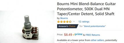
There are dedicated centre detent blend pots, e.g. Bourns PDB182-GTRB
https://www.mouser.co.uk/datasheet/2/54/pdb182-gtrb-1571270.pdf
https://www.mouser.co.uk/datasheet/2/54/pdb182-gtrb-1571270.pdf
That is the exact one that I have. I am not totally lost just way off track and do not know exactly where to go from here. I do know I need to wire the pots inversely but even doing this will make the volume change between either end of the pots and the center detent. I am trying to come up with a way to keep the volume at whatever point it is set at throughout the range of the pots. Maybe I should be looking at the volume control more than the signals going into it.
Attachments
My goal is to have a true control between 2 passive pickups on a telecaster guitar with no volume or tone fluctuations. The hard part is getting 100% of the signal one while getting 0% of the other on both ends of the pot but also getting 100% of both of them in the center detent. You guys are always thinking of better ways than I can come up with. Thanks for all of the help in advance.
If you don't want " tone fluctuations " ,
why have the control ?
I always considered going between
neck and bridge pickups as a
tone control ....
why have the control ?
I always considered going between
neck and bridge pickups as a
tone control ....
I want tone fluctuations. What I don't want is unexpected volume fluctuations.
OK so passive is not going to get it done. Now I am looking at this circuit and using an onboard 9 volt battery for a power supply. What would be good opamps to use? Would R values still be 10K?
OK so passive is not going to get it done. Now I am looking at this circuit and using an onboard 9 volt battery for a power supply. What would be good opamps to use? Would R values still be 10K?
Attachments
Last edited:
Can you explain why the blend pot you have doesn't give you what you want?
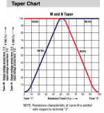
It is specifically designed to give 0/100, 100/100, 100/0 at positions 0, 5, 10.
It will give you the same function as the 3-way switch, but with gradation in between. Page 2 of the data sheet shows the response you showed in post #7.
It is specifically designed to give 0/100, 100/100, 100/0 at positions 0, 5, 10.
It will give you the same function as the 3-way switch, but with gradation in between. Page 2 of the data sheet shows the response you showed in post #7.
Attachments
Haha, no worries, but try it first and check it does what you need, it should work, but make sure there are no spurious responses.
I think it's just a case of wiring the pickups to the opposite terminal of each pot, the other ends to ground, then both centre pins to the tone pot and jack.
I think it's just a case of wiring the pickups to the opposite terminal of each pot, the other ends to ground, then both centre pins to the tone pot and jack.
- Home
- Live Sound
- Instruments and Amps
- Balance/Blender circuit instead of 3 way switch