Putting the tweeter in between the two midbass drivers only excacerbates these lobing and power response issues, because of the increased distance between the two midbass drivers.
There are no two ways about this.
While I agree with you Vacuphile regarding vertical directivity issues, there are many people who like the sound of MTM arrangements. I personally do not care for the sound.
I started a thread last year to discuss this, and after 150+ posts there was no consensus reached
MTM sound characteristics
So to be fair to LSspeaker, we should acknowledge that MTM architecture is liked by some, disliked by others, and he will have to make up his own mind.
Hi Dave,
Sorry but your explanation doesn't make a lot of sense to me.
Conserning the Zobels, I'm not sure how you will compensate for the rising impedance of a woofer just by changing the values of your crossover...
Anyway, the zobels don't have anything to do with this issue.
I'm also not sure how you can compensate for baffle step losses just by "playing" with the values of the crossover itself.
Not ment to be rude or whatever 😉
Passive crossovers (as TMM stated) are subtractive. you can't "boost" frequencies (well there is one exception with high Q filters but this doesn't apply here).
A larger inductor starts the baffle step compensation rolloff around 100Hz. Lookup the electrical transfer function. you'll then probably find you dont need a 3rd order crossover to hit your target.
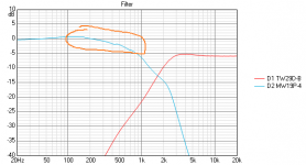
Take a look at the attached electrical transfer function (this is a graph of the crossover effect on the drivers - not the actual acoustic response of the drivers). In orange is the bafflestep compensation being applied. You'll note the gradual 6dB rolloff from ~ 150Hz to 200Hz. This was achieved by using a larger value series inductor for the woofer.
Yes this will cause the crossover point to become lower... because you must alter / remove unnecessary components in your woofer circuit. You will therefore get the crossover you need AND BSC in one go.
PS: your 40uF tweeter capacitor is almost redundant too. I think this could be removed / reworked to reduce the size (and therefore cost) if you are intending polyprop / quality capacitors.
Attachments
Zobel networks are required if you need to have constant impedance. This is for 3 reasons:
1. you have a crossover (textbook values - always a bad idea) that only work with constant impedance
2. you have an amplifier that is not impedance / phase swing friendly - and needs a constant load.
3. You are intending to crossover a driver where the impedance is rapidly rising with increasing frequency and you need the impedance maintained to reach your target rolloff
I don't think any of the above 3 apply in your case.
Your woofer only varies ~ 3 Ohms - 2 octaves either side of your Fc (crossover point). Why are you bothered with a zobel? there is no point here.
It can be done properly using either of the methods mentioned above... as long as the problem is understood and addressed. The circuit being chosen to suit the convenience of your method.
Looking at the original circuit you have used impedance compensation at the driver so your BSC could see a consistent load.
However, you didn't use more compensation before the BSC circuit so that it sees a constant source impedance and so your low pass filter sees a constant load.
Looking at the original circuit you have used impedance compensation at the driver so your BSC could see a consistent load.
However, you didn't use more compensation before the BSC circuit so that it sees a constant source impedance and so your low pass filter sees a constant load.