Trying to learn to understand why certain frequencies are hard to get good when building passive crossover filters, and how the baffle size, shape, width and edges create different "problems".
And can i somehow anticipate the response, by building a certain baffleshape?
Or is a certain width and high "always" better for a certain size driver ?
For example:
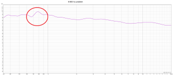
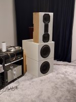
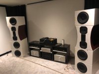
Ivé build a MTM with 8 inch mids and a AMT tweeter, and have a "irregularity" i like to get better between 600-800 hz.
Sadly i haven´t got a microfone when i had the MTM i the original baffleshape with straight even sides, and after i rebuild the baffle as last picture shows i´ve seems to have hard to get the 6-800 hz "small problem" away.
Any thoughts on baffle and baffels in general ?
Best regards John
And can i somehow anticipate the response, by building a certain baffleshape?
Or is a certain width and high "always" better for a certain size driver ?
For example:
Ivé build a MTM with 8 inch mids and a AMT tweeter, and have a "irregularity" i like to get better between 600-800 hz.
Sadly i haven´t got a microfone when i had the MTM i the original baffleshape with straight even sides, and after i rebuild the baffle as last picture shows i´ve seems to have hard to get the 6-800 hz "small problem" away.
Any thoughts on baffle and baffels in general ?
Best regards John
Attachments
It sounds as though you are trying to mix up the diffraction generated response variations rather than trying to reduce the diffraction.
Hi, kind of, and you can see it by taking spinorama measurements, mesuring the speaker/a transducer from multiple angles and interpreting the results.And can i somehow anticipate the response, by building a certain baffleshape?
Or is a certain width and high "always" better for a certain size driver ?
Basically surroundings of the transducer have effect on the sound, size and shape of the structure matters. For example sharp edge like a baffle edge diffracts sound, sound goes around the corner and doing so a back wave is emitted in opposite polarity in backwards direction. Basically the baffle edge becomes secondary sound source as sound from the transducer had various time delays reaching the edge at various points and diffracting, also path length from the edge to observation point is probably different than from direct sound.
On very long wavelengths, that are say 10x the scale of the baffe just go around, the box is practically invisible to the sound. As frequency goes up, shorter wavelengths diffract and reflect on the structure until at some frequency wavelength is shorter than the transducer emitting it which makes beaming, less sound toward the edge when the on axis response is equalized ~flat. From this you can reason that bandwidth, whose wavelength is perhaps few times the baffle size all the way up to transducer size and some beyond will diffract around the baffle and produce this secondary sound source at the edge.
Now when you have multiple sound sources, a transducer and baffle edge, separated by distance and also time delay in this case, you'd see an interference pattern in a frequency response. If you measure the speaker from another angle, the interference changes as the sound source(s) are now at different distance from the mic and relatively to each other. What this means is that on some particular frequency there might be dip towards some direction and a peak towards some other direction. For this reason the problem is not fixable by EQ but the physical structure needs to be fixed that the sound would be quite similar to all (important) directions.
How to get rid of this? Remove the edge. You can also minimize the bandwidth where this happens, basically by reducing flat baffle area around the transducer to minimum, bring baffle size ~= transducer size.
Then, some drivers have huge flat areas embedded like tweeters usually do. Sometimes you want to be practical and use some certain size baffle for some other reason. So, in this sense its not one size fits all.
Such peak/dip pattern could come from a resonance as well but the spinorama helps to identify diffraction for example. Sometimes many things happen and affect and might be hard to decipher which one is it, or is there something else. The diffraction you can anticipate, its around baffle size wavelength and above. You could use some simple diffraction tool to try and match features of the response.
Since most speakers are say 20-50cm in size, their problems show up in these wavelengths, around 1kHz which is 34cm long.
Last edited:

It sounds as though you are trying to mix up the diffraction generated response variations rather than trying to reduce the diffraction.
Not quite get what you meaning AllenB.
And reduce diffraction how ?...the edges ?
Regards John
You can also minimize the bandwidth where this happens, basically by reducing flat baffle area around the transducer to minimum, bring baffle size ~= transducer size.
Thank you for the explanation!
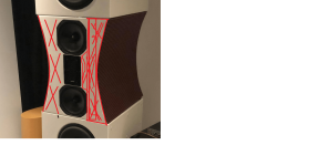
So if i do like my pic shows and take all Red marked surface away, it will be less inpact on response?
Regards John
Attachments
Remove it or chamfer it. The latter keeps your design possible and actually might give the best outcome.
Hi, kind of, and you can see it by taking spinorama measurements, mesuring the speaker/a transducer from multiple angles and interpreting the results.
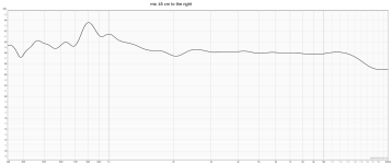
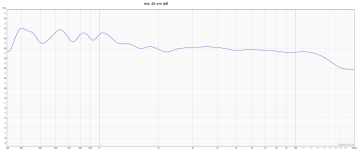
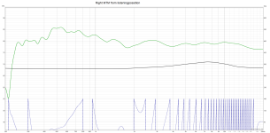
Have taken 3 more mesaurements, all from 1 meter.
One from 1 M in front of tweeter Red line
One from 1 M but mic 45 cm to the left from center tweeter Blue line
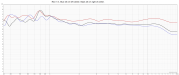
And Black line is mic 45 cm to the right of tweeter center.
So it seems that sound to the right of center speaker (i.e inside) makes this happend.
From the left its more like smaller waves.
Observe it´s 1 dB scale!
Regards john
Attachments

Yeah it would reduce diffraction related interference in frequency response.
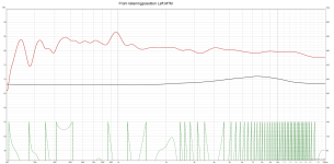
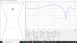
You can estimate the effect what a big round over would do with VituixCAD diffraction tool. Here is somethign along the way, 20x100mm ribbon on ~20cm x 40cm baffle with crude shape. With and without 50mm radius roundover there is quite difference on the axial response:


Remember, overall directivity changes a bit, bafflestep might change frequency and so on. For very least make (spinorama) measurements and adjust crossover after you are done.
You can estimate the effect what a big round over would do with VituixCAD diffraction tool. Here is somethign along the way, 20x100mm ribbon on ~20cm x 40cm baffle with crude shape. With and without 50mm radius roundover there is quite difference on the axial response:
Remember, overall directivity changes a bit, bafflestep might change frequency and so on. For very least make (spinorama) measurements and adjust crossover after you are done.
Hard to say, is your measurement windowed to rule out reflections from the environment? This is usually something like 3-4ms before floor / ceiling reflection if you measure at home, speaker mid of typical ~2,5m room height. This is so short window that resolution is lost under ~1kHz quite fast and many of the diffraction effects hide in such measurements. Yours have lots of ripple below 1kHz so I suspect its interference, reflections from the room boundaries / objects near the measurement rig.Have taken 3 more mesaurements, all from 1 meter.
One from 1 M in front of tweeter Red line
One from 1 M but mic 45 cm to the left from center tweeter Blue line
And Black line is mic 45 cm to the right of tweeter center.
So it seems that sound to the right of center speaker (i.e inside) makes this happend.
From the left its more like smaller waves.
Regards john
See VituixCAD measurement manual how to take measurements of multiple angles, links top of the main page https://kimmosaunisto.net/
To evaluate how much diffraction you have between two different constructs (new and old box) you can measure just on axis of any driver, its got about the worst interference which should reduce when there is less diffraction, which means its probably less audible if it was audible in the first place.
Note, Its not enough to use this one measurement to make very good crossover, as the speaker radiation to all directions (power response) is needed to be able to make good compromises on the crossover for best possible sound. The axial response can show good response with many crossover variations, while differences lurk in power response. Analyzing the measurements from multiple directions help to judge what problems there are and how to get around them, whether building new structure that measures better or just juggle the crossover for best compromise if in hurry. If you have years of practice behind you might get by by less measurements for good results.
Perhaps, it may also increase the diffraction produced.take all Red marked surface away, it will be less inpact on response?
Your measurement is wrong. As the speaker is symmetrical the left and right measurements should be identical.Have taken 3 more mesaurements, all from 1 meter.
One from 1 M in front of tweeter Red line
One from 1 M but mic 45 cm to the left from center tweeter Blue line
And Black line is mic 45 cm to the right of tweeter center.
The only possible explanation is that you didn't gate the measure, but this is not how you should measure a speaker.
Ralf
if someone is interested on the edges, ripple tank simulator can be tweaked to exaggerate the effect and simplified into 2D plane. The edge makes secondary sound source towards listener, which would be top of this screen. Its supposed to be kind of top down view showing what happens when sound meets the edge.
http://www.falstad.com/ripple/Rippl... w+0+422+857+422+382 P+1+488+279 P+1+372+276

http://www.falstad.com/ripple/Rippl... w+0+422+857+422+382 P+1+488+279 P+1+372+276
Last edited:
Your measurement is wrong. As the speaker is symmetrical the left and right measurements should be identical.
The only possible explanation is that you didn't gate the measure, but this is not how you should measure a speaker.
Ralf
Don´t have possibilitys to do exact mesaurements due to placement of mic, and cant get it in exact position equal when i move it left to right.
Also left wall have 70 mm stonewool and air behind the "visual" wall, and not the same speakerplacement regarding distance to nearest wall etc.
Broken back and neck and trying the best i can to make some sense in my mesaurements, 215 kilo speakers isen´t a good combo either.
How does it measure at the listener seat ?
Here is the first one, suddenly the "vobble" between 6-800 hz, move to a bigger at 960 hz ??
And cant read out the phase plot
Back hurts like hell, must take a small pause and some strong things.
Regards John
Attachments
Your measurement is wrong. As the speaker is symmetrical the left and right measurements should be identical.
The only possible explanation is that you didn't gate the measure, but this is not how you should measure a speaker.
Ralf thank you
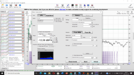
Could you show me a typical mesaurement with the "right " gate?
Just that i can studdy the mesaurement and try to learn someting from the settings.
So many settings in REW and this is the options i have after clicking the Measure button.
Regards John
Attachments
Hard to say, is your measurement windowed to rule out reflections from the environment? This is usually something like 3-4ms before floor / ceiling reflection if you measure at home, speaker mid of typical ~2,5m room height. This is so short window that resolution is lost under ~1kHz quite fast and many of the diffraction effects hide in such measurements. Yours have lots of ripple below 1kHz so I suspect its interference, reflections from the room boundaries / objects near the measurement rig.
See VituixCAD measurement manual how to take measurements of multiple angles, links top of the main page https://kimmosaunisto.net/
To evaluate how much diffraction you have between two different constructs (new and old box) you can measure just on axis of any driver, its got about the worst interference which should reduce when there is less diffraction, which means its probably less audible if it was audible in the first place.
Note, Its not enough to use this one measurement to make very good crossover, as the speaker radiation to all directions (power response) is needed to be able to make good compromises on the crossover for best possible sound. The axial response can show good response with many crossover variations, while differences lurk in power response. Analyzing the measurements from multiple directions help to judge what problems there are and how to get around them, whether building new structure that measures better or just juggle the crossover for best compromise if in hurry. If you have years of practice behind you might get by by less measurements for good results.
Thanks for a very informative post tmuikku 👍
Have begain with the program VituixCAD recently, and its much to learn for an old goat 😉
But a fantastic program.
Regards John
I would play a little with the loudspeaker positionning to look for better magnitude curve to figth that peak - Teflon pad below the speaker for the back or plate with wheels.
At looking one of the measurement from the seat, one of the speaker doesn't have the evil bump... I would continue in that process of let and rigth + merged measurements from the seat with the mic at your ears heigth (around 80/90 cm according your size and sofa most of the time for non papou audiophiles). Look if you can smooth things before a hard redesign process.
At looking one of the measurement from the seat, one of the speaker doesn't have the evil bump... I would continue in that process of let and rigth + merged measurements from the seat with the mic at your ears heigth (around 80/90 cm according your size and sofa most of the time for non papou audiophiles). Look if you can smooth things before a hard redesign process.
You can estimate the effect what a big round over would do with VituixCAD diffraction tool. Here is somethign along the way, 20x100mm ribbon on ~20cm x 40cm baffle with crude shape. With and without 50mm radius roundover there is quite difference on the axial response:
Okey, so i have enter the 210 x 210 mm drivers in VituixCAD, and try to make the auctual "shape".
The same curve if i move the "mic" in the program to the lower midrange.
And its only ½ dB down at 900 hz if i rise the edge rad to 50mm.
But dont know how its supouse to look, or whats bad or good.
Regards John
Attachments
Hi, you can put round drivers, use Sd (area) for size, something around 220 for 8" driver.
The simulator shows response towards mic, ideal pistonic transducer output and diffraction with the edge combined. You can use the two woofers if you wish or just one, and mic where ever you wish, what ever you wish to inspect. You can utilize the system like you want, for example if you want to explore how shape and size of the baffle affects woofers response listening on axis of the tweeter, you can do it by moving the mic where the tweeter would be. Then watch what happens to the response if you resize the baffle. I like to take screenshots and then compare them, easy to see how response changes by cycling between them.
The diffraction tool produces similar "measurements" as the measurement manual suggests to do with real speaker and real mic. You can follow the measurement guide: use one transducer, move the mic on axis, export the data and load it to a driver on the main window. Now you have opportunity to see response to all directions. In reality there would be some additional ripple on the responses, real drivers aren't ideal, backside (bulk) of the box is not included so its effect to the response is missing, its ideal situation, transucer and edge. You can learn a lot from it if you compare things in relation. If you are interested on measured 600Hz wiggle, model your current baffle with the ideal drivers, and if you don't see similar ripple in the diffraction tool response its something else in your measurements than diffraction that makes the particular wiggle, reflection from the room or something else.
If it does, then resize the baffle, or try the roundovers what their effect is and so on, until the wiggle is gone. Imagination to use, try to match the simulation to reality, and vice versa 🙂
Last edited:
Unfortunately I use Arta so can't help on the settings in REW. But basically the right gate is the gate that in the time domain contains only the direct sound without the reflected sound. See here for a useful doc on the procedure for Arta: FR measurement using ARTACould you show me a typical mesaurement with the "right " gate?
Just that i can studdy the mesaurement and try to learn someting from the settings.
So many settings in REW and this is the options i have after clicking the Measure button.
Regards John
BTW Arta is free
Ralf
- Home
- Loudspeakers
- Multi-Way
- Baffleshape and SPL response for drivers