Meaning, if I have an 8" wide baffle, and that is how the speaker was designed, can a person add a big round over on the edges, and not mess up things? Or would that be effectively adding baffle width?
One rude example ... say I had a large 3" diameter wood dowel, and it was cut into fourths. Leaving large quarter rounds. If I then attached two of those quarter rounds, one on each side, would that mess up the sound of the existing speaker?
One rude example ... say I had a large 3" diameter wood dowel, and it was cut into fourths. Leaving large quarter rounds. If I then attached two of those quarter rounds, one on each side, would that mess up the sound of the existing speaker?
Adding any extension to the baffle effectively increases it's dimension, a round-over simply helps to minimize diffraction on that edge. As to it's effect, it would depend if the baffle is the front side of a box or just a plank 8" wide. If it is just a plank it would only just slightly change the roll-over frequency( F equal) for the driver, nothing to worry about. Even less so if the round-over is attached to the baffle of a box.
C.M
C.M
Depends to what extent the designer compensated for edge diffraction in the crossover. While roundovers reduce edge diffraction at high frequencies which is an improvement, the unmodified crossover may now compensate for peaks and dips in the on-axis response that no longer exist, so the response may end up worse than without the roundovers.
If adding roundovers to an existing design, I would assume half of the roundover to be part of the front baffle and the other half to be part of the side panel.
So if you add quarter-rounds made from a 3" dowel either side of an 8" flat baffle, you are effectively adding ~0.75" (half of a quarter round) to each side of the baffle so it is now effectively 9.5" wide, even though the entire cabinet is physically 11" wide.
Conversely, if you built the 8" wide cabinet speaker with square edges, but then ran a 1.5" diameter router roundover bit down each side, you've effectively narrowed the baffle by 0.75" on each side, so it is now effectively 6.5" wide (and the flat portion of the baffle would now only be 5" wide, and of course the cabinet is still overall 8" wide).
Therefore, to achieve the same effective width as the square edged 8" baffle, the flat part of the baffle has to be 6.5" wide and the overall width of the cabinet 9.5". This should achieve the same low frequency diffraction response as the square edged 8" baffle, but less with ripple in the high frequencies and the ripples would still occur at the same frequencies as before.
Last edited:
In this post some pics and measurements of added generous roundovers
https://www.diyaudio.com/forums/mul...lled-directivity-loudspeaker.html#post6018417
https://www.diyaudio.com/forums/mul...lled-directivity-loudspeaker.html#post6018417
It is very easy to test the effect of added roundovers, like Patrick did. Make some half round bars/tubes out or any material available (cardboard tube or plastic sewer pipe) and tape them on the sides! When you get the effect you want, take some more time and effort to find a way to make pretty ones!
I don't think adding the half tubes is an entirely accurate experiment because there's still an acoustical impedance mismatch where the half-round tubes meet the sides at a 90degree angle. To make it accurate the tubes need to be blended into the sides. Perhaps with some 'false sides' made of foam board to make the cabinet taper from the now wider front to the narrower back. Even after doing that, you've added more than just a roundover - the baffle has been increased in width also which will itself produce a significant effect.
Acoustic impedance mismatch is what causes edge diffraction in the first place. At low frequencies the mismatch is insignificant and the acoustic waves wrap around to the rear of the box. At high frequencies there is almost total reflection when the acoustic wave reaches the edge of the baffle as there is a significant impedance mismatch, which causes the wave to propagate forward instead of around to the sides. Because there is some delay between the sound being produced by the driver and being reflected at the edge, you get constructive and destructive interference at the listening position between sound directly from the driver and that of the edge reflections. The result is ripples in the frequency response at the listening position. Placing the drivers asymmetrically on a baffle and/or making the baffle a clever 2D shape (still having 90degree edges) can be an effective way at making all the edge reflections partially cancel each other out - at least at the on-axis listening position. Off-axis, the reflections may no longer cancel.
Adding roundovers or bevels produces better impedance matching than a 90degree corner, so higher frequencies (those with a wavelength smaller than the roundover) propagate around the edge as if it wasn't even there, instead of total reflection occurring. The result is smoother response both on and off axis. The roundovers have to be big to be effective though. If your roundovers are only 10% of the baffle width, you've only improved the edge diffraction by 10%... So the only way to defeat edge diffraction is to have a baffle which is 100% roundover (a sphere). Even small roundovers do look aesthetically pleasing though.
Last edited:
Yes !!! This is the info I was looking for. For clarification, these are regular Carrera speakers, built exactly to Paul's design. So they are 8" wide with square edges. They sound just perfect. But they would look waaaaay better if I added HUGE roundovers. But i do not want to screw up my sound.
And this is what concerns me ... "If adding roundovers to an existing design, I would assume half of the roundover to be part of the front baffle and the other half to be part of the side panel".
So I kind of figured I would be adding width to the cabinets baffle, with really large roundovers. I guess the question becomes, will the roundovers provide more benefit , or will they screw up the Carreras intended sound ? Looks like building mock up roundovers, and testing them is the only way for sure. I sure with Paul would see this and weigh in.
Since a 1.5" radius should only affect the higher frequencies, and this would be about ups and downs but on average no significant difference in the crossover itself, this seems like a simple operation.
I suspect you might even be OK increasing the treble a little after this.
I suspect you might even be OK increasing the treble a little after this.
I am already building the temporary prototype roundovers.
So I will test it first.
I am not the speaker builder people on this site are. So i was wondering what sound differences i should expect to hear. I truly would not know. But would love to know what the large roundovers are doing technically, and how much change would really be heard/ noticed.
So I will test it first.
I am not the speaker builder people on this site are. So i was wondering what sound differences i should expect to hear. I truly would not know. But would love to know what the large roundovers are doing technically, and how much change would really be heard/ noticed.
Don't be surprised if you don't notice anything at first. Diffraction is easier to hear when you turn the volume up.. staying cleaner longer. It is also IMO easier to notice when you suddenly take it away.
Instead or with prototyping we can always use simulations that support roundovers, like
Loudspeaker Design Software
Software
One problem is that I don't know how roundovers are simmed, do they add or reduce flat baffle dimensions?
You can search diyaudio.com for other threads on this subject "roundover, diffraction"
https://www.diyaudio.com/forums/search.php?searchid=21912656
A tight package of general info
Basic article | Baffle geometry
Extremely difficult to hear those changes anyway. With pink noise perhaps, but only with quick change... That's because the differences are limited to narrow range and are minimal in amplitude. Just believe the measurements!
Last edited:
Those measurements are not good. They do not show the time difference or other things unique to the diffraction,
What do you mean with "those measurements"? I have understood that for human hearing amplitude response dominates in this case , becuse edge diffractions happen so early that they must be counted in "direct sound" ie. first few milliseconds. Even phase cannot be heard at those frequences where edge diffracions happen.
Earl Geddes talks about audibility of nonlinearities here Diffraction Is More Audible Than Nonlinear Distortion!? The link to his original paper is broken, but I guess it is this http://www.gedlee.com/Papers/AES06Gedlee_ll.pdf
Anyway, now we are talking about very very small changes in rectangular baffle dimensions and roundovers! Room and environmental acoustics are a different story!
A paper with some math models of edge diffractions, does this help?
http://www.torean.dk/artikel/Diffraction.pdf
Last edited:
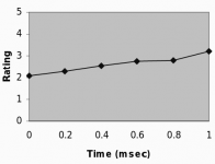
According to Earl's original paper, there was a link between the audibility of an amplitude variation, and the amout of delay, beginning at zero (image from page 33 of the presentation).
I've done my own mathematical polar models of diffraction. The ones you show are very nice. However unless I have missed something it seems beyond their scope to show the audibility of a secondary source against its source angle, or against its delay time.
I have heard the direction that nearby secondary sources are coming from.A paper with some math models of edge diffractions,
I've done my own mathematical polar models of diffraction. The ones you show are very nice. However unless I have missed something it seems beyond their scope to show the audibility of a secondary source against its source angle, or against its delay time.
Attachments
Studies about human hearing, localization
The effect of an additional reflection in a precedence effect experiment
In reverberant environments, a sound emitted from a source can propagate such that a person receives a direct sound and multiple reflections of that sound at the ears. In order for a person to determine the location of a sound source in a reverberant environment, the auditory system must extract the relevant location information from the direct sound and disregard conflicting information from the reflections. The various phenomena of the “precedence effect” indicate that the auditory system weights the localization information in direct sound or first wavefront more heavily than that in the later arriving reflections (see Blauert, 1997; Litovsky et al., 1999 for reviews). The perceived locations of the sources change depending on the delay between the direct sound (also called the lead) and reflection (also called the lag) (Wallach et al., 1949; Zurek, 1980; Gaskell, 1983; Yost and Soderquist, 1984; Saberi and Perrott, 1990; Shinn-Cunningham et al., 1993; Tollin and Henning, 1998; Stellmack et al., 1999; Litovsky and Shinn-Cunningham, 2001). When the lead-lag delay is very short (less than 1 ms), listeners perceive a single fused sound at a location somewhere between the actual locations of the lead and lag, referred to as “summing localization” (Warncke, 1941; Blauert, 1997). For delays greater than 1 ms but less than the threshold for hearing two separate sounds (i.e., an echo), the directional information from the lead dominates the perceived location of the fused auditory image, called “localization dominance.” In the range of delays where localization dominance is observed, listeners have difficulty discriminating changes in the location of the lag, called “lag discrimination suppression” (Litovsky et al., 1999; Litovsky and Shinn-Cunningham, 2001). As the delay is increased, changes in the directional information of the lag become easier to discriminate. In fact, for long delays (greater than 10 ms for clicks), the directional information in the lag may be easier than the lead to discriminate (Stellmack et al., 1999) or localize (Litovsky and Godar, 2010). In these cases, Stellmack and colleagues postulated that listeners became confused about which source to report the location of, and thus often responded to the location of the most recently occurring source. This effect has been called “temporal-order confusion” (Stellmack et al., 1999; Litovsky and Godar, 2010).
Flight time of sound to 5" (10" wide baffle with a tweeter in centerline) is 0.000409s (0,4ms)
Last edited:
- Home
- Loudspeakers
- Multi-Way
- Baffle width ... can it be changed in a particular way?