I've read a lot about baffle step and I think I have a good grasp of what it is and does. What I don't understand, and I can't seem to find a clear reference to, is the relation one should strive for between it and the selected crossover point.
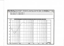
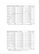
I have already built mid/high enclosures for a 3 way system. They have very smooth response down to 350hz, with a couple dB variation (a little dip, then a little rise) down to 125hz. I am designing the bass bins now, and I can make the baffle almost any width within reason. I want to actively cross (slope not yet determined) the mid/hi enclosure to the bass bins around 350hz, so I can use the bass bin power amp to compensate for efficiency differences. The bass bin consists of two 8" woofers that have smooth response up to around 1k, then a gradual rise to break up around 3k. How wide should the baffle be to integrate the baffle step with the crossover point?
Any ideas about what order filter to use for the active?
Attached are scans of response curve of actual mid/hi enclosures, and woofers.
Peace,
Tom E
Attachments
Have you modelled or corrected for the baffle step loss already for the mid/top enclosure?
Typically you can select the baffle width/xover point such that the highpass placed on the midrange driver can compensate for the loss created by baffle step. In other words if you place a highpass on the driver around the frequency that baffle step occurs, providing the driver is perfectly flat and the xover is textbook, you will have a dip around the xover point, due to the loss created by bafflestep. You can then play with the Q of the highpass filter to correct for the loss.
However as you're going active this simplifies matters somewhat as a shelving network can be used to correct for the theoretical loss created by baffle step. The equations shown on Linkwitz's website will show you how to calculate the correct component values.
After that all you should need is the actual low and high pass filters. I'd go with 4th order electrical, even if you don't need it, simply so you've got extra flexibility should it be needed. If it turns out that you only need the 2nd order electrical you can always bypass the extra circuitry.
Baffle step will occur at the freq determined by 115/width (metres) of your mid cabinet.
If you make that width co-incide with your xover freq, then a simple 1st order crossover will do. If going active, a simple passive line level xover is the easiest.
If you make that width co-incide with your xover freq, then a simple 1st order crossover will do. If going active, a simple passive line level xover is the easiest.
Thanks for the response. Let me know if I've got this right.
You mean that the xover point should coincide with the baffle step -3dB point? Baffle step is really a misnomer, as there is no distinct step but rather a slope that spans more than an octave. So I should plan to have the -3dB point of that slope equal to the xover center frequency, in this case, 350hz?
That would make the front baffle appx 13" wide, which is perfectly acceptable. I'm thinking large (1 - 2" wide?) 45 degree chamfers on the cabinet edges would help to smooth ripples in the response. I read in another thread that half of the total chamfer width should be considered part of the total baffle width.
I guess the slope of the xover would have an effect on how much I need to play with the xover to get it to flatten the response. You think varying filter Q would suffice? While I know what that means, I am not sophisticated enough to know how to do it, but I'll try to learn. I've gotten this far!
I don't know yet which active xover to use. It's a common topic here, and I've researched many available but never found one I consider ideal for a reasonable amount of money. Maybe I expect too much. I already have a cheap electronic one, and it sounds perfectly terrible. I'm sure I could build a better one from a kit. I am not very interested in the sound of digital filtering, but its flexibility is tempting for experimental purposes.
Peace,
Tom E
re:'You mean that the xover point should coincide with the baffle step -3dB point?' well, that's up to you, it just simplifies things a bit...
re:'Baffle step is really a misnomer, as there is no distinct step but rather a slope that spans more than an octave' - well you could size the baffle step components for ~ 1 octave lower & adjust the amount of compensation with your level control...
Passive Line-Level Crossover
re:'Baffle step is really a misnomer, as there is no distinct step but rather a slope that spans more than an octave' - well you could size the baffle step components for ~ 1 octave lower & adjust the amount of compensation with your level control...
Passive Line-Level Crossover
I've read a lot about baffle step and I think I have a good grasp of what it is and does. What I don't understand, and I can't seem to find a clear reference to, is the relation one should strive for between it and the selected crossover point.
Tom E
Certainly for most 2-way systems the baffle step frequency range and crossover points are far removed. I would never consider setting crossover point by baffle step issues.
It is easily possible with passive crossovers to compensate for the broad effects of baffle step. The primary series inductor largely determines midrange level and lets you set that region to match the bass region. Most designers wll be working with either in-room curves or free field (anechoic) curves and will inherently be compensating for any 4pi to 2pi effects in the design process. Unless they directly compare near field curves to free field curves, the 4pi to 2pi effects won't be considered in isolation, they just become one of the factors that shape the "raw material" of woofer/cabinet response.
For your 3-way design it is clear that you already have good response with your 2-way mid/top module, (so baffle step must have gotten fixed along the way). For the LF part the interaction with the room and nearby boundaries will be much greater than effects due to baffle width.
Don't worry about it.
David S.
- Status
- Not open for further replies.