I mean is the above circuit right? Secondly take an example of a Scanspeak 10 inch driver https://www.scan-speak.dk/product/26w-8861t00/ which is 88.5dbWhat is your question....
Yes, baffle step has an effect usually reaching up into the midrange. In a basic sense it can be fixed with just an inductor. In a medium sense it needs more components. In a deeper sense it cannot be fixed, only compensated.
and a 3 inch dome midrange at 91db and tweeter at 91db.
so if we use baffle step compensation take about -4db or -6db will the overall gain of the woofer will be eaten up by the baffle step to 82.5db?
What Im expressing is if you attenuate the mid and highs to consider 88.5db technically they have to be flat but like the baffle step is being affected the lower rolloff need to be considered hence we apply the BSC so my point in there is since we are attenuating the mid and highs in this scenario the overall sensitivity of the speaker would go much lower than 88.5db?
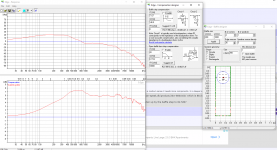
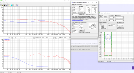
This one doubt is literally making me mad can you please clarify on this. Some of the responses before and after BSC is attached in here using Edge.
Attachments
"Baffle Step to even effect the midrange" - a good reason to make the baffle step frequency the crossover freq. for woofer - mid
Yes.since we are attenuating the mid and highs in this scenario the overall sensitivity of the speaker would go much lower than 88.5db?
If you want to choose a circuit and a response, we may be able to simulate it and see that it works.
I mean is the above circuit right?
Not enough info to answer that yet, sorry.
Every crossover circuit needs to be designed to work with the actual frequency & impedance responses of the specific drivers, which I don't see mentioned on your previous attachment, so we have no way of knowing if it's right or not.
Even if we had the driver models, their response is affected by box characteristics like baffle width, so a circuit that's right for Driver X in Box A could still be wrong for that driver in a wider or narrower box.
so if we use baffle step compensation take about -4db or -6db will the overall gain of the woofer will be eaten up by the baffle step to 82.5db?
Yes, the net sensitivity of the overall loudspeaker system is reduced by however much bafflestep compensation you use, that is correct.
Hi,
If it is not too much off topic: is it feasible to passive crossover at the middle of the baffle step level (F3) with a second order low pass with a high Q : Butterworth or Cheybysheff ? The little bump could feel a little the step loss below the F3 baffle step cut off?
The steeper roll off could bealso better to tame woofer high frequencies break ups of rigid cones.
But what about group delay in the hundred of hz area where ou brain has more delay sensivity ? Could it be mixed with a second order Linkwitz Riley. What about power response trade off VS group delay trade off in the overlap filter area?
I am also looking foe a BSC without an added serie coil and resistor. In my case the woofer is a 8" and the baffle step F3 is around 445 hz (28 cm width cabinet). So I plan a littlier 3 dB BSC and deal with the front wall and loudspeaker spacing to compensate the uper bass area between Helmotz frequency of the room and the F3 baffle step (445 hz).
Bad idea ?
I feel the effect of BSC is felt into sub 50Hz as well. I mean sonically. I read it somewhere that conventional without BSC if we fix the overall freq response in a sim software then if another version with BSC its said that the BSC sound had better bottom end tonality. I dont know how it actually works that way.
Secondly if there is a -6db of BSC then you will mostly see speakers at max with 86db sensitivity but we see even 89db as well so are these companies applying BSCs in their design?
Secondly if there is a -6db of BSC then you will mostly see speakers at max with 86db sensitivity but we see even 89db as well so are these companies applying BSCs in their design?
Hi,
Bsc is 4 octave wide with the -3db point at the middle of those 4 octave so depending of the width of your baffle it may indeed have an effect in the sub region.
I own loudspeakers which are 54cm wide with the -3db point around 220hz ( without bsc in their native passive filter as they were designed to be located onwall) so the whole range the bsc i introduced (by using a high shelf filter attenuating the high around the 220hz pivot point) when turning them active dsp filtered is from 55hz to 880hz.
I rarely used more than 4db attenuation in the different rooms and config i used them and i don't see you'll ever find a full 6db used anywhere ( except outdoor). This will make the loudspeaker too bass heavy in 99% of case you'll face. This is often a grief with 2.5 way for example ( where you have native +6db compensation from the driver arrangement) where they need big space and be located far away from boundary ( at least with passive filters).
Manufacturers will make an average assumption of around 3db max ( much less for bookshelf) as they don't have hands on on where they'll be located and room size.
In pro field monitors usually have configurable bsc control to adapt to room and location ( if you make inwall monitors you'll need to reduce the bsc to negative amount - cut- rather than boost lows).
I'm thinking this has come from a specific design.if you make inwall monitors you'll need to reduce the bsc to negative amount
I don't know if it was specific to a design Allen, i've come across at least 2 case where it was needed to lower the amount of bass once the monitors was in place in wall.
Of course the loudspeakers i talk about was designed to be used freestanding (they were initially nearfield monitors) by designer and not to be inwall mounted. Iirc we needed something like 6 to 9 db low shelf cut ( around 200hz) to have them to behave as they should have once inwall.
The Atc SCM110a i used in the last control room i built had a 'bsc compensation' knob to adapt them to the mounting condition ( they were designed with both freestanding and inwall situation allowed).
Makes sense, so it's not that in wall design requires reverse compensation it's just that these models do relative to the default mounting condition.
Ahah! Typical you see the other side of the coin! 🙂
But i'm sure we will agree there isn't many commercial loudspeakers designed with 2pi radiation in mind.
But i'm sure we will agree there isn't many commercial loudspeakers designed with 2pi radiation in mind.
correct, Infact if you look at the onwall speakers the sensitivity could be higher because there is no step.Makes sense, so it's not that in wall design requires reverse compensation it's just that these models do relative to the default mounting condition.
Hi,"Baffle Step to even effect the midrange" - a good reason to make the baffle step frequency the crossover freq. for woofer - mid
So if one crossover on the middle of the baffle step diffraction, how to make the whole power response flat, please without exta inductor baffle step correction?
A resistor in // with the low pass inductor to flaten the 3 db raise till the XO and on the high pqss of the medium just a resistor in serie before the caps to adjust the spl level according the woofer bass unit spl level ?
correct here is the catch. If you have narrow baffle which is true in most of the cases your baffle step tends to get into low mid region as well. Definitely its not linear so just an Lpad will not solve the case as the falloff is not linear. Hence I feel that using the baffle step considering even the mids is important. Hence I have posted above circuit which affects the mid as well. If you have wider baffle the mid is not affected as much and the standard xover for mid will be sufficient. Highs doesnt make sense.Hi,
So if one crossover on the middle of the baffle step diffraction, how to make the whole power response flat, please without exta inductor baffle step correction?
A resistor in // with the low pass inductor to flaten the 3 db raise till the XO and on the high pqss of the medium just a resistor in serie before the caps to adjust the spl level according the woofer bass unit spl level ?
In 2 way you just need to have BSC for midbass driver as it has both mid and low job done by one driver.
It can look worse on-axis than it is on average, so adjusting for some of the bumps in the response won't be the best way to go.the falloff is not linear
First order approximation of baffle step is 4560/(baffle width in inches).
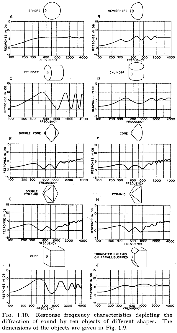
The transition from 2π to 4π has ripple that depends on the shape.
dave
The transition from 2π to 4π has ripple that depends on the shape.
dave
I am surprised that no one has mentioned another bsc technique. Using a 2nd driver at the back of the cabinet, which has it's own baffle step loss, mirroring the front driver. Works best with widish shallowish cabinets. Rear driver usually has a lp filter.
^Hi, interesting, so much so that here is a little experiment with ideal drivers 🙂
It is ideal 8" driver on ~20cm wide 1m high baffle.

Same driver copied, flipped to emulate back side of 30cm deep cabinet. This simulation does not include full enclosure so there would be some more ripple in real situation or in BEM simulation. Delayed sound from back to front, the "reverse bafflestep" makes dip on the front response making the "step" appear worse, now with additional dip! DI goes negative ~200Hz, as it represents relation of sound power to axial response, all three visible in the Power & DI graph.

Low pass on the back gets rid of the highs on the back, but also cause more delay to the back sound in form of group delay and the "step" and dip are still there. This doesn't seem to change with filter frequency or order, since they would cause more delay and only move the dip lower in frequency. Can't get the peak cancel out even with high low pass (kHz) because the path length difference from back to front is not cancelled, we need to reverse time to make it happen. Making box shallower changes the dip a bit, but the dip is there as long as there is any depth to the box, delayed sound from back to front.

But yes we can reverse time, by delaying the front driver! Here I used negative delay on the simulator instead because it was easier 🙂
Yes, baffle step gone!

And with delay and low pass to get rid of the high frequencies on the back. Note there is still some diffraction, shows as hump. This would be better or worse in real box with actual dimention to it, roundovers, baffle width in relation to transducer size and what not. Basically the baffle step is gone though.

But, delays are DSP land and with DSP baffle step is not an issue even with single front driver. Well, it is an issue but it doesn't cost any extra to EQ it flat, other than the max SPL capability lost in the process.
Flipping polarity of the back driver would make some kind of dipole or cardioid system depending on relationship of the delay, dimensions and filter(s). This would be nice system and kind of get rid of baffle step, but would require compensating the lows as well since they would drop to 6dB per octave instead of <6dB of closed box bafflestep.
Here is the previous system, where baffle step was defeated, but with flipped polarity on the back driver, and only with the low pass.

ps. polar maps are normalized to highlight effects of the system to polar pattern.
It is ideal 8" driver on ~20cm wide 1m high baffle.
Same driver copied, flipped to emulate back side of 30cm deep cabinet. This simulation does not include full enclosure so there would be some more ripple in real situation or in BEM simulation. Delayed sound from back to front, the "reverse bafflestep" makes dip on the front response making the "step" appear worse, now with additional dip! DI goes negative ~200Hz, as it represents relation of sound power to axial response, all three visible in the Power & DI graph.
Low pass on the back gets rid of the highs on the back, but also cause more delay to the back sound in form of group delay and the "step" and dip are still there. This doesn't seem to change with filter frequency or order, since they would cause more delay and only move the dip lower in frequency. Can't get the peak cancel out even with high low pass (kHz) because the path length difference from back to front is not cancelled, we need to reverse time to make it happen. Making box shallower changes the dip a bit, but the dip is there as long as there is any depth to the box, delayed sound from back to front.
But yes we can reverse time, by delaying the front driver! Here I used negative delay on the simulator instead because it was easier 🙂
Yes, baffle step gone!
And with delay and low pass to get rid of the high frequencies on the back. Note there is still some diffraction, shows as hump. This would be better or worse in real box with actual dimention to it, roundovers, baffle width in relation to transducer size and what not. Basically the baffle step is gone though.
But, delays are DSP land and with DSP baffle step is not an issue even with single front driver. Well, it is an issue but it doesn't cost any extra to EQ it flat, other than the max SPL capability lost in the process.
Flipping polarity of the back driver would make some kind of dipole or cardioid system depending on relationship of the delay, dimensions and filter(s). This would be nice system and kind of get rid of baffle step, but would require compensating the lows as well since they would drop to 6dB per octave instead of <6dB of closed box bafflestep.
Here is the previous system, where baffle step was defeated, but with flipped polarity on the back driver, and only with the low pass.
ps. polar maps are normalized to highlight effects of the system to polar pattern.
Last edited:

Bipolar projects have been done.
https://www.diyaudio.com/community/threads/bipolar-mltl-speaker-with-fr125s-wr125s.61753/Somewhere on one such thread they mention that putting the rear and front drivers at different heights somehow mitigates the bipolar dip. Don't know how that works.
https://www.diyaudio.com/community/threads/bipolar-mltl-speaker-with-fr125s-wr125s.61753/Somewhere on one such thread they mention that putting the rear and front drivers at different heights somehow mitigates the bipolar dip. Don't know how that works.
I think KII speakers have done that boundary interference cancellation in DSP well thats one positive point but such things change from room to room from speaker position to position. There is no much control over it in passive system. The concept here is to see the baffle step happening properly. There are other ripple effects in the frequency response which baffle structure comes into play. Well too many things to consider as you know.^Hi, interesting, so much so that here is a little experiment with ideal drivers 🙂
It is ideal 8" driver on ~20cm wide 1m high baffle.
View attachment 1014561
Same driver copied, flipped to emulate back side of 30cm deep cabinet. This simulation does not include full enclosure so there would be some more ripple in real situation or in BEM simulation. Delayed sound from back to front, the "reverse bafflestep" makes dip on the front response making the "step" appear worse, now with additional dip! DI goes negative ~200Hz, as it represents relation of sound power to axial response, all three visible in the Power & DI graph.
View attachment 1014562
Low pass on the back gets rid of the highs on the back, but also cause more delay to the back sound in form of group delay and the "step" and dip are still there. This doesn't seem to change with filter frequency or order, since they would cause more delay and only move the dip lower in frequency. Can't get the peak cancel out even with high low pass (kHz) because the path length difference from back to front is not cancelled, we need to reverse time to make it happen. Making box shallower changes the dip a bit, but the dip is there as long as there is any depth to the box, delayed sound from back to front.
View attachment 1014564
But yes we can reverse time, by delaying the front driver! Here I used negative delay on the simulator instead because it was easier 🙂
Yes, baffle step gone!
View attachment 1014565
And with delay and low pass to get rid of the high frequencies on the back. Note there is still some diffraction, shows as hump. This would be better or worse in real box with actual dimention to it, roundovers, baffle width in relation to transducer size and what not. Basically the baffle step is gone though.
View attachment 1014566
But, delays are DSP land and with DSP baffle step is not an issue even with single front driver. Well, it is an issue but it doesn't cost any extra to EQ it flat, other than the max SPL capability lost in the process.
Flipping polarity of the back driver would make some kind of dipole or cardioid system depending on relationship of the delay, dimensions and filter(s). This would be nice system and kind of get rid of baffle step, but would require compensating the lows as well since they would drop to 6dB per octave instead of <6dB of closed box bafflestep.
Here is the previous system, where baffle step was defeated, but with flipped polarity on the back driver, and only with the low pass.
View attachment 1014578
ps. polar maps are normalized to highlight effects of the system to polar pattern.
- Home
- Loudspeakers
- Multi-Way
- baffle step compensation methods