for gladiator ci11…..😀😀
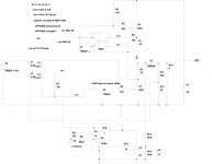
R10 and R8 form a 5k trim pot
Yes, SIR!! You have tamed that Siemens beast with kindness. Way to go, generg!
Oh no ci11,
The IRF version is only for you to hear some sound out of the circuit.
Till the power MOSFET beasts are really tamed by someone more clever.....🙂))
The IRF version is only for you to hear some sound out of the circuit.
Till the power MOSFET beasts are really tamed by someone more clever.....🙂))
Oh no ci11,
The IRF version is only for you to hear some sound out of the circuit.
Till the power MOSFET beasts are really tamed by someone more clever.....🙂))
Yes, I think you can definitely hear the sound of this gladiator being surrounded and tortured by 2 giant Power MOSFET beasts!!
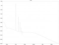
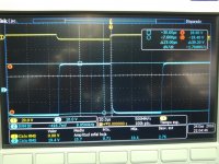
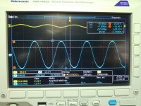
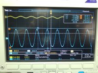
and here two pictures that show how tiny changes in bias voltage make big effects.
first picture V bias = 3.49 and voltage out the output node 42.67V
second picture Vbias = 3.58V and voltage at the output node 607mV
Ha, Ha no easy circuit even for simulating gladiators…..🙂
whomever send these to OPLDF , I promise to further optimize it
(in a decade or two)

Attachments
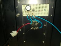
Assuming everything is connected up properly, and the opto is working as intended, the bias should be throttled lower by the increasing conduction of the transistor in the opto coupler. So in the first instance, we need to measure the voltage across the led (better yet across the 100r resistor feeding the led) in the opto and confirm that it is increasing as the mosfet heats up and begins to draw more current. If we find that the voltage here is behaving as we expect, then measure the voltage across the collector - emitter of the transistor in the opto. That should be falling.
If that works but the bias is still headed up in a hurry we need to make the bias compensation more sensitive - perhaps by increasing the 10k resistor to say 12-15k and see how we go from there.
Just my 2cents....apologies if this had already been covered in one of the earlier posts.
If that works but the bias is still headed up in a hurry we need to make the bias compensation more sensitive - perhaps by increasing the 10k resistor to say 12-15k and see how we go from there.
Just my 2cents....apologies if this had already been covered in one of the earlier posts.
Last edited:
whomever send these to OPLDF , I promise to further optimize it
(in a decade or two)
That is so GREAT, Aleksandar!
😀😀😀
Now I can start my experiments with this circuit, just waiting for the semi monsters.
I hope all the guys that bought the parts outside will see this!
Otherwise they will have some trouble using them.
Assuming everything is connected up properly, and the opto is working as intended, the bias should be throttled lower by the increasing conduction of the transistor in the opto coupler. So in the first instance, we need to measure the voltage across the led (better yet across the 100r resistor feeding the led) in the opto and confirm that it is increasing as the mosfet heats up and begins to draw more current. If we find that the voltage here is behaving as we expect, then measure the voltage across the collector - emitter of the transistor in the opto. That should be falling.
If that works but the bias is still headed up in a hurry we need to make the bias compensation more sensitive - perhaps by increasing the 10k resistor to say 12-15k and see how we go from there.
Just my 2cents....apologies if this had already been covered in one of the earlier posts.
yes , you're right , we need combo of ,say , 8K2 fixed resistor series with 10K trimpot there
I wrote about adjusting that resistor earlier , but it is certainly not visible as dedicated post
just for info , attached images taken from previously posted pdf's
refer to them for proper readability
whatever , if this works , we can make it work with bipolar supply , sans output cap
Attachments
Last edited:
That's Quant Asylum's soon-to-come audio analyzer: QA405 and QA401 Status - QuantAsylum
I'd prefer this alternative unobtainium: http://www.diyaudio.com/forums/equipment-tools/277808-diy-audio-analyzer-ak5397-ak5394a-ak4490.html
nope
however , it seems of all people having exact experience with those puck parts , only Papa is smart enough and qualified to decipher what's happening
discrepancy between his experience and ci11's .........
however , it seems of all people having exact experience with those puck parts , only Papa is smart enough and qualified to decipher what's happening
discrepancy between his experience and ci11's .........
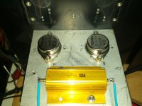
Hello all. This will be, surely, my last adventure into sit land. Before begin, I want to give thanks to Nelson (what can I say), Michael Rothacher (lamp, frakentracer, .. designs), Steve (ci11 forum member that told me the mosfet to use and he was my motivation), Esteban (dady), Gerd (generg), Soundhappy, Tim, WalterW, and a lot of fantastic people I had knew here.
This is one variation of lamp design. But carry all to limit (at least for me).
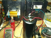
I have upper power supply to 80Vdc, and current to 6A. So, we get 50Wrms with a 4 ohm load.
The main problem was one CCS that could works to this current and dissipate a lot of power. I have tried some devices, first, IXFN140N20P, but I did not worked for me (broken one mosfet and one THF51). Sure that this device works very well here, but I am not very smart and sure other persons better me will be able to do it. Later, I tried with one semisouth, R063. Now it worked, but heat dissipation seemed me a lot for one TO247. At last, speaking with Steve (ci11 member), told me try other device of IXYS, IXTN46N50L, linear power mosfet. WOW, works very well for me. CISS is a lot and sure will be others devices a lot better here, but for me it is OK. I can regulate ccs current from a little to 7 o 8 amp easily. And I measured stability and there was one very little variation of 40 or 50 mA, I think.
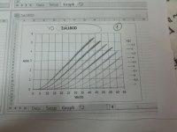
And for getting this output power at 4 ohm it is necessary almost 6A. So, looking curve of 2sk180D I own, I saw that with 6A I am very near to low vgs zone. I need low current, to half, 3A and for voltage, more or less 35 or 40V, so I am away from low vgs zone. But voltage is then 80V.
All these values are one BIG problem. I have used two bigs heatsinks but they are not enough (250W on CCS and other 250W in two parallel vfets). I need bigger one, that I will get soon.
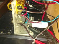
Attached are 2sk180 curve (identical for both vfets) and mounted circuit.
This is one variation of lamp design. But carry all to limit (at least for me).
I have upper power supply to 80Vdc, and current to 6A. So, we get 50Wrms with a 4 ohm load.
The main problem was one CCS that could works to this current and dissipate a lot of power. I have tried some devices, first, IXFN140N20P, but I did not worked for me (broken one mosfet and one THF51). Sure that this device works very well here, but I am not very smart and sure other persons better me will be able to do it. Later, I tried with one semisouth, R063. Now it worked, but heat dissipation seemed me a lot for one TO247. At last, speaking with Steve (ci11 member), told me try other device of IXYS, IXTN46N50L, linear power mosfet. WOW, works very well for me. CISS is a lot and sure will be others devices a lot better here, but for me it is OK. I can regulate ccs current from a little to 7 o 8 amp easily. And I measured stability and there was one very little variation of 40 or 50 mA, I think.
And for getting this output power at 4 ohm it is necessary almost 6A. So, looking curve of 2sk180D I own, I saw that with 6A I am very near to low vgs zone. I need low current, to half, 3A and for voltage, more or less 35 or 40V, so I am away from low vgs zone. But voltage is then 80V.
All these values are one BIG problem. I have used two bigs heatsinks but they are not enough (250W on CCS and other 250W in two parallel vfets). I need bigger one, that I will get soon.
Attached are 2sk180 curve (identical for both vfets) and mounted circuit.
I need adjust better the circuit with current and bias to get best distortion as I can.
And try adjust with 8 and 16 ohm.
I want to measure output impedance too. Simulations with LTSpice show me over 2 ohm, but I want really measure.
And try adjust with 8 and 16 ohm.
I want to measure output impedance too. Simulations with LTSpice show me over 2 ohm, but I want really measure.
I want to add my sincere thanks and congratulations to JAMA for his incredible work! A 50W Class A Single-Ended amplifier that shows a perfect square wave at 10kHz while swinging 40V peak to peak into 4 Ohm is not only an incredible circuit accomplishment, but it will shine where it counts - playing music. His motto "never surrender" is constantly on display, and I am humbled and honored to have witnessed this tremendous feat along the process.
Bravo, JAMA!
Bravo, JAMA!
- Status
- Not open for further replies.
- Home
- Amplifiers
- Pass Labs
- BAF 2015 Coverage