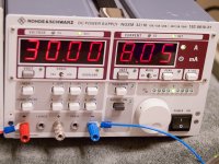
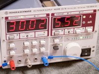
Yep - one supply to lower half, battery biased at 4V73, output at 30V, 3A22. See photos. This means the bias regulator is somehow not coping well with these devices, right?
EDIT: spoke a little too soon - at 4V71, the current kept drifting up until it pushed past 3V2 and the voltage drops due to CC operation in the supply. Perhaps the device is the problem?
The current will drift up due to temperature coefficient of device once the device reaches thermal equilibrium, current should be steady.
It's not easy guessing what you are observing so I'm just throwing out possibilities of what you are seeing.
besides trying Papa's idea ... I never liked CC function of bench supplies
it behaves more as limiter than CC Source
what's happening if you put CC function off ?
I wasn't aware he was using that.
Turn that bloody thing off, or at least increase it to 4A just as safety device not as constant current source.
Also please try increasing R6 (genergs schematic) to 50k to reduce current through circuit.
Would be nice if someone attached Papa's circuit so we are all referencing same part numbers
Would be nice if someone attached Papa's circuit so we are all referencing same part numbers
well , I wasn't , too .
It's like playing chess blind folded. Hahahaha
Also please try increasing R6 (genergs schematic) to 50k to reduce current through circuit.
Would be nice if someone attached Papa's circuit so we are all referencing same part numbers
I still insist on trying halves separately on 30V , without any current limiting (well , 6A3 fuse will do )
edcor's input grounded - it must work that way .
and yes - for lower half - setting Iq in steps , 'till temp equilibrium
.... blind folded........
double (that)
I wasn't aware he was using that.
Turn that bloody thing off, or at least increase it to 4A just as safety device not as constant current source.
2pD - I knew it would drift up as it thermally stabilize, but did not think it would go crashing through like it was. According to the schematic, it would be +60V in and 3A2 draw. I set the current limit to 4A5 and it was crashing into all the time, and dropping voltage as result of having the switch on CC and not FB.
ZM - The CC/FB switch is a safety device on my supplies. In the FB position, it just switches output off as opposed to dropping voltage. Strapping 2 supplies requires me to leave it on CC.
I have now put the bias supply back in at 4V71, and will bump the CC/FB to 4A and see if it stabilizes at 3A2. It may take a very long time to get there.
Yeah. I agree starting with lower power rails to sort this out, 30V to 40V is a good place to start and turn off current limiter on supply.
2pD - I knew it would drift up as it thermally stabilize, but did not think it would go crashing through like it was. According to the schematic, it would be +60V in and 3A2 draw. I set the current limit to 4A5 and it was crashing into all the time, and dropping voltage as result of having the switch on CC and not FB. .
Ok. Understand whats happening now.
Do as ZM suggest drop power supply to 30V and turn off current limiter.
Let's see where the current stabilizes at.
CC causes wacky stuff. I've had issues only to discover that the CC knob wasn't fully CW.
Yes me too. It's given me plenty of headaches even recently trying to bias p channel mosfets.
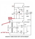
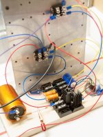
just to be on same page , two piccies :
Ok I understand what you are saying now.
I'd probably suggest 20V only initially as safety precaution to see where the current stabilizes on upper fet.
Turn off current limiter. See where current sits at. Provided it's not ridiculously high, then increase supply.
just to be on same page , two piccies :
Again, CC/FB is only the option to either drop voltage or cut output. The limit is whatever I set it to be. For the last tests, I actually just set the supply to 30V 8A and it tried to crash through. See pictures.
I will now try the 2 pix from ZM.
Attachments

The upper part of circuit must be the problem as bottom half is limited by top half.
But it will still be nice to see what drain current you get with 4V7 on lower part of circuit.
But it will still be nice to see what drain current you get with 4V7 on lower part of circuit.
just to be on same page , two piccies :
On first picture - left - 0.01A or negligible draw.
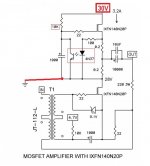
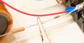
Wiring picture shows picture 2 on the right. 5A53 draw and STEADY. This turns on the upper device and it stabilized at about 175°. No runaway. Lower device is cool. The devices are arranged on the heatsink like the schematic - upper is the bias regulator and the lower is the output.
Attachments
- Status
- Not open for further replies.
- Home
- Amplifiers
- Pass Labs
- BAF 2015 Coverage