Can someone please explain me why this amp sounds bad? Is there bad iron or schematic is not optimal, personally I would do phase splitter differently. I've build one PP KT88 amp and it sounds very good. Here I have no clue why Grant is so bad.
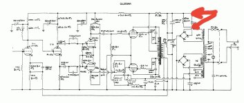
This is the only schematic, which can be found online.

This is the only schematic, which can be found online.
There is no cathode resistor for the power tubes. How do you measure and adjust the bias?
If it the bias is not right, it will sound bad.
If it the bias is not right, it will sound bad.
The power tubes are fixed bias, there is a negative voltage supply in the schematic. The lower bridge rectifier sends (-) voltage to VR2, which adjust the bias of the power tubes.
and I don't know much about P-P amps but maybe that phase inverter isn't biased correctly. That would corrupt the signals passing to the power tubes. The only voltage shown on the schematic is 480V at the PT, have you measured any voltages in the amp? Perhaps an incorrect b+ is affecting bias of the preamp section.
and I don't know much about P-P amps but maybe that phase inverter isn't biased correctly. That would corrupt the signals passing to the power tubes. The only voltage shown on the schematic is 480V at the PT, have you measured any voltages in the amp? Perhaps an incorrect b+ is affecting bias of the preamp section.
That's a Williamson circuit and there's nothing inherently wrong with it, that I can see. It seems that there is no way to measure the output tube's bias. If they are not adjusted properly the amp is not going to sound as good as it should. A 10 ohm resistor needs to be inserted between the cathode of each output tube and ground, and the DC voltage across those resistors will help properly bias the tubes. If the amp can't be modified, a set of sockets for measuring bias might work:
https://www.amazon.com/Nobsound-Vac...8&psc=1&mcid=dc576d2c4ff837d78e688a970bccc804
There is also a pot, VR1, to balance the driver stages. If this is not set properly, there will be a lot of distortion going to the output stage. Voltages at the plates of V2a and V2b should be checked to make sure they are roughly equal. The proper way to check this pot is with a 'scope, but if that isn't available, making sure the plate voltages of V2 are equal is the next best thing.

There are TWO bias adjust pots, one for each output tube. But no way to determine the idle current being drawn by each output tube.
If you measure the voltage on the 2 ends of capacitor C2, you can deduce the current running through the 2 Kt88 bulbs. We adjust VR2, VR3 so that the G1 of the 2 Kt88 bulbs has the most negative value, then the 2 Kt88 bulbs are considered not to conduct. Then gradually adjust VR2, VR3 to have the current running through the Kt88 bulbs at the desired value of about 50 mA ÷ 60 mA (based on the voltage change on the 2 ends of capacitor C2). You can adjust it like that and see how it goes.
But before that, you need to make the 2 tube V2a, V2b work in balance by adjusting Vr1 so that the voltage at pins 1 and 6 of the 2 tube is equal.
But before that, you need to make the 2 tube V2a, V2b work in balance by adjusting Vr1 so that the voltage at pins 1 and 6 of the 2 tube is equal.
Attachments
Can someone please explain me why this amp sounds bad? Is there bad iron or schematic is not optimal, personally I would do phase splitter differently. I've build one PP KT88 amp and it sounds very good. Here I have no clue why Grant is so bad.
This is the only schematic, which can be found online.
What is the value of the feedback resistor at the front driver? It's not printed. Did you install one...of what value?
Execution?
Withoiut working the detaikls i’d loose at least one of the first 2 gain stages and the phase splitter turned into a proper LTP with a CCS.NDo what you wish wish the output stage bias.
Iron plays a big role, as does the power supply. Not exactly sure what is happening withthe dual bridges, buyt better diodes (Schottky), and some poly caps (poly).
We did similkar with Grant Fidelity KT88 amp, also moved to EL34s. I have a set of unused O’Netics OPTs for it, but we’ll save thise for something better,
dave
Masa1897,
There are some things I like in Your schematic in Post # 11, Versus the schematic in Post # 1.
First, if a Ultra Linear output transformer is properly wound:
There is very little leakage inductance from the UL tap to the plate tap. And if properly wound, there should be very little leakage inductance from the plate tap to the secondary windings.
In that case, there is no need for the Series RC from plate to UL tap of Post # 1. That looks like a bandaid for a poorly wound output transformer.
Second, with the driver stage, there is a common 680 Ohm resistor for the parallel cathodes.
A good feature of Un-bypassed 680 Ohms is it provides balancing of the two triode gains, so there is no need for the balancing pot, VR1, that is in Post # 1. Instead, use very well matched plate load resistors, and no VR1.
If an ECC82's two triode sections are badly balanced, replace the tube (I can purchase well balanced JJ ECC82s for circuits that need that).
Post # 11 kept out any bypass cap there (good).
My JJ KT77 tubes are better than my EL34 tubes.
My low power amplifiers are usually 2 stage, I usually use a CCS common cathode phase inverter/driver, and the output stage.
I also use a single ended driver and self inverting output stage.
My latest low power amps are balanced, but require the balanced XLRs of my CD player.
For higher power amplifiers than mine . . .
I agree with planet10.
Use a LTP (CCS) phase inverter, followed by drivers, and than outputs. The is 3 stages, but still requires 4 triodes and 2 output tubes.
(I am not a fan of concertina phase inverters, even though I have heard excellent amplifiers that use them; there are tradeoffs).
I prefer the phase inverter first, because LTPs/CCS inverters have less gain, and less dynamic range, Versus the next stage such as the drivers that are used in Post # 1 and Post # 11.
$0.03
adjusted for inflation
Last edited:
With 3 stages: CCS phase inverter, driver pair, and pp output . . .
if you want to use Global Negative Feedback, then the 2nd grid of the CCS phase inverter is a real good place to apply the NFB.
Note: Watch out for all the phase inversions . . . all the way from the phase inverter, driver, output stage, and output transformer.
You do not want to make a power oscillator.
What is the exact diagram for the led comparator in post 11? Values and components type are missing and it’s connected to…?
Regards, Gerrit
Regards, Gerrit
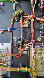
Today I have some time to tinker with amps. One of them not let you to adjust bias, found out that 100 Ohm resistor, witch connects grid 2 of KT88 to the output transformer for UL mode are toast. Measured anode voltage it is 570 V, negative supply for bias is for one KT88 can be adjusted and is about -65 V, another one is something -80 V. And both KT88 have cathode 10 Ohm resistor, on the picture is voltage measured across this resistor.
Here its better to understand how it is connected, in my amps values can be different.What is the exact diagram for the led comparator in post 11? Values and components type are missing and it’s connected to…?
Attachments

As you posted, the Ia current of the 2 Kt88 bulbs is very different. One bulb is 0.27v and the other is 0.435v, almost double. You need to adjust it to have the same value and it is probably more reasonable to change the value of the bulb from 0.27v to 0.435v.
I too have seen many amps of this Williamson configuration.....and found them extremely good sounding except using 6CG7/6SN7 interstage..(some better sounding than many 3 stage amps with LTP). My first modification is to replace that ECC82 for a better tube, and what is the resistor value for the interstage step network it isn´t shown ? I assume the circuit uses 20dB global feedback.
The ECC82 has to drive into quite a load as it is already a moderately high distortion tube. The most important safety consideration is to modify/drill chassis for a couple of Bias access points (see pic example) . The presets adjustable with a trimmer through ventilation holes or elsewhere. I´d do anything to avoid upending the chassis with dangerous near 600V B+ lurking. A slipped probe can make an almighty bang and destructive if Ohmmeter is accidentally set to amps !! I´ve done it and probably others too.
Break KT88 cathode circuit, put 10R 1-2W wirewounds in each leg to ground: and wire cathodes to access sockets to correctly ascertain the correct currents using the Volts setting. A little degeneration does no harm and reduces distortion.

Let Ohms law do the rest.
Bench Baron
The ECC82 has to drive into quite a load as it is already a moderately high distortion tube. The most important safety consideration is to modify/drill chassis for a couple of Bias access points (see pic example) . The presets adjustable with a trimmer through ventilation holes or elsewhere. I´d do anything to avoid upending the chassis with dangerous near 600V B+ lurking. A slipped probe can make an almighty bang and destructive if Ohmmeter is accidentally set to amps !! I´ve done it and probably others too.
Break KT88 cathode circuit, put 10R 1-2W wirewounds in each leg to ground: and wire cathodes to access sockets to correctly ascertain the correct currents using the Volts setting. A little degeneration does no harm and reduces distortion.
Let Ohms law do the rest.
Bench Baron
With 3 stages: CCS phase inverter, driver pair, and pp output . . .
if you want to use Global Negative Feedback, then the 2nd grid of the CCS phase inverter is a real good place to apply the NFB.
-------------
This is exactly on the LTP 3 stage concept of my parallelled P_P 225W amp, except uses a power interstage driver with 12GN7´s. One or two more mods on this, I scrapped the first stage RC snubber (wrong place) and made balanced snubbers on each LTP ouput to ground or B+, also a sub freq LF step filter included to the next stage. A recommended route. The snags, plenty of them:- LF step filter values depend on our old friend, the output transformer characteristics and all the other LF poles within the amp. There isn´t any design that the output transformer has so much influence. Have fun !
Bench Baron
So, now this thread can be also repair attempt🤣.
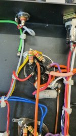
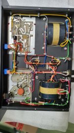
Today I've changed resistors from grid 2 of KT88 to OT. And now I can adjust bias on both tubes😏, but not for long time, it endet up in spectacular firework inside one of KT88😅. And also it took grid 2 resistor, wich I have replaced and original installed was burnt. I've repaired many of tube amps and build some, I think this seams to be a faulty KT88. OT must be OK, but I need to measure it. And some pictures of amp, white things inside KT88 after firework)
Today I've changed resistors from grid 2 of KT88 to OT. And now I can adjust bias on both tubes😏, but not for long time, it endet up in spectacular firework inside one of KT88😅. And also it took grid 2 resistor, wich I have replaced and original installed was burnt. I've repaired many of tube amps and build some, I think this seams to be a faulty KT88. OT must be OK, but I need to measure it. And some pictures of amp, white things inside KT88 after firework)
Attachments


- Home
- Amplifiers
- Tubes / Valves
- Bad sounding Grant G100 AMS KT88 Amp