I must have stuck my head somewhere we should not discuss.
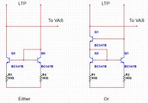
Playing around with possible "improvements" I dropped a Wilson current mirror into my input stage. Absolutely normal LTP, ccs and mirror, light degen etc driving a very conventional Darlington single side VAS
FAIL. It drove one side to the rail. This is with the feedback transistor and the added Wilson transistor in the negative (feedback) leg. Yet, if I reverse legs, it works. (does cut the offset in half, even while it raises the distortion by an insignificant smidge)
What the #%*& am I missing?
Hi tvrgeek, can you pls drop a schematic sketch here so that we fully understand what it is?
BR, Valery
BR, Valery
Umm... I mean... that's the only way it works )
Comparing to simple mirror, Wilson one will always be "backwards", otherwise, at the other side, you always have Vbe * 2 offset (plus some small addition because of the emitter resistor) from the rail. So it will always send the output to the rail the other way round.
Is that what you mean? )
Comparing to simple mirror, Wilson one will always be "backwards", otherwise, at the other side, you always have Vbe * 2 offset (plus some small addition because of the emitter resistor) from the rail. So it will always send the output to the rail the other way round.
Is that what you mean? )
Attachments
Well, that is exactly what it was doing. Seems odd none of the text books mention this at all. I find very few places where it was implemented, and some did not have it backwards, leading me to believe they never tested their design.
I now still have no idea if it is worth it. In simulation, no; but simulation does not take into consideration my level of matching of the various input pairs.
Thanks, I thought I was loosing what little mind I had left.
I now still have no idea if it is worth it. In simulation, no; but simulation does not take into consideration my level of matching of the various input pairs.
Thanks, I thought I was loosing what little mind I had left.
Well, that is exactly what it was doing. Seems odd none of the text books mention this at all. I find very few places where it was implemented, and some did not have it backwards, leading me to believe they never tested their design.
I now still have no idea if it is worth it. In simulation, no; but simulation does not take into consideration my level of matching of the various input pairs.
Thanks, I thought I was loosing what little mind I had left.
I've used the wilson both for "blameless" CM's and for "symasym" type
VAS's. NO real gain in either case , just one more device.
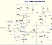
Believe me , if it mattered ... the "badger" would have a wilson based CM. 🙂
PS - about 1-2 PPM (in simulation) improvement. More can be gained
by tweaking TMC or optimizing operating V/I for various devices in
the design.
OS
Thanks for the conformation. I have been spending a lot of time doing just that. Improvements by the dB are to be had. Some SOP seems well founded, some not.
I have posed the question to several folks, when is the IPS "good enough" that further improvements are completely swamped by other variables? Only working on paper at this point as we all respect reality does not match simulation, so chasing numbers in Spice is not guaranteed to be a pleasurable amplifier. Unless demonstrated though, optimizing a given topology for minimum numbers will likely be an improvement. In the MX-50, increasing the driver stage current by a mA halved the simulated distortion. Can't hurt. Swapping from Miller to TMC cut it by 8 dB. Changing my Hafler from lag compensation to TMC was a slap in the face more clean. (That one IS is hardwware, playing right now)
I had an idea for a possible way to improve quiescent current, but it seems it is easier to beat me up than to express alternative ideas. I may be an idiot some times, but not a perfect idiot. No one is perfect 😀
Transformers came for my bench test amp. All black wires. Don't you just love the Chinese?
If you are willing to consider the Wilson3 current mirror (3 transistors), why not also consider the Wilson4 current mirror (4 transistors)? They both appear in the same figure in D.Self's power amp book; in the 6th edition that's Figure 6.9 on page 133. It solves a fairly big problem with the standard Wilson3, as Self points out.
Beware: just as with all the other current mirrors on that page, there is a "right" way to assign the current_in and current_out legs of the Wilson4 mirror; and there is also a "wrong" way to assign the legs. Fortunately, D.Self shows the right way.
Or you could consider the 4 transistor "cascode current mirror"; see page 21 of (Phillip Allen's Georgia Tech lecture notes) for the schematic.
I plan on modeling them for my education, but I don't see any real advantage. If I was going to add two transistors to the IPS, it would be to cascode the amplifier. If a better mirror gives an improvement from .00111 to .00112, but a miliamp bias changes by .01, which should I worry about? When does matching be hundreds of times more important? Note the Wilson actually increased the simulated distortion by .0002%, but the offset was cut in half. I did not do new noise simulations.
I had not seen PA's paper. Looks good. thanks. Self, Cordel, and Leach are covering so much, they don't have some of the depth I wish.
I pretty much have my "Reasonable" design tuned as well as the basic architecture will allow. Same with my low voltage version of the MS-50.
I will be building the bench version of the MX50 this weekend, but on the bench, there is a limit to what I can measure. I have no way of measuring THD-9 @ 20K using a sound card. Frequency or resolution.
Cascode - "bang for the buck" !!
Yes ! do the cascode ....
You -
A. can use lower Vsat CM/LTP semi's .
B. many more options for devices (lower Vce).
C. higher Z at cascode will lower THD more than a wilson CM.
I used a zener as cascode reference on the "badger". There is
another "way". Either reference it between rail and the LTP CCS with 2 resistors (badger option or luxman) ... the crude way !
OR add a emitter follower off the main LTP CCS for a
"isolated" reference and use a LED "string" or zener/diode/led (D3-11 /Q15 - below) to get the desired voltage.
I was told this will not show as reduced THD (it stays the same) ,
but will impart "magic" 😀 upon the soundstage.
All I know is that it is a valid (electrically) ... way to implement the cascode.
OS
Attachments
+1If you are willing to consider the Wilson3 current mirror (3 transistors), why not also consider the Wilson4 current mirror (4 transistors)? [snip] It solves a fairly big problem with the standard Wilson3...
This Wikipedia article shows both versions, and how to connect them.
edit: There's an interesting comment in there about the frequency response as well. I don't remember seeing that mentioned before.
Last edited:
Cascode
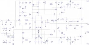
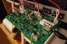
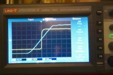
As an example - my implementation of the cascode (rather simple, but no problem). I've got 2 LTPs "upside down" against each other, so CMCL improves the balancing ability in situation of real elements tolerance.
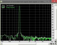
This is a live prototype and practically measured spectre for 1 kHz signal. OP is not shown on schematic.
As an example - my implementation of the cascode (rather simple, but no problem). I've got 2 LTPs "upside down" against each other, so CMCL improves the balancing ability in situation of real elements tolerance.
This is a live prototype and practically measured spectre for 1 kHz signal. OP is not shown on schematic.
Attachments
- Status
- Not open for further replies.
- Home
- Amplifiers
- Solid State
- Backwards WILSON current mirror?