Farnell will sell us 1000 sst4118 @ 98p each
Is 1000 the minimum order quantity? That is unusually high for Farnell.
I have never heard of anyone suggesting that a jFET can be used/wired as a transdiode.
Where do you get your information?
Same place where you eventually got it too - application notes. 😀
Some time ago I was involved with a project about detecting / measuring electrostatic charge and I went through all the possible combinations of "protection diodes". For the mentioned application, the problem is that the diodes leakage will severely diminish the sensitivity of the detector. Or will plainly drive it into saturation. Have a look at something like the LMP7721 and try to evaluate what happens if you connect jellybean diodes between the inputs and the rails or some other crude "ESD protection" scheme. (fortunately the mentioned op amp has the diodes already included, however older siblings not always did).
Don't forget that in normal operation (i.e. the output signal's dV/dt is below the slew rate limit), the opamp input pins are at the exact same voltage. So the input protection diodes have zero volts across them.
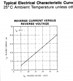
Here's the dataBOOK curve of leakage current vs reverse voltage for a 1 picoamp diode, the FJH1100. They measure leakage current at 5 volts of bias. Notice the slope; as reverse voltage goes up, so does diode leakage. As reverse voltage goes down, so does diode leakage. At the normal operating point of an opamp (Vin+ == Vin-) the diode voltage is zero and extrapolating the curve, diode leakage is much MUCH less than 1 pA.
Now observe that the MMBF4117 (non-A) JFET is specified to leak less than 10pA at 20 volts of reverse bias. How much does it leak at the normal operating point of an opamp, zero volts of reverse bias? A whole lot less than 10pA. This is good news: leakage at the real life operating point, is way WAY less than leakage at the worst case operating point used in final test at the diode & JFET factory.
_
Attachments
Don't forget that in normal operation (i.e. the output signal's dV/dt is below the slew rate limit), the opamp input pins are at the exact same voltage. So the input protection diodes have zero volts across them.
Correct for an ideal op amp, except in practice this "normal operation" happens only if:
- the input signal is well conditioned in amplitude and spectrum
- the op amp's load capacitance is sufficiently low
- the opamp works alone or is part of a larger circuit with a very limited form of global feedback
Here's another article on protection schemes from AD :
http://goo.gl/oqIi5d
See pages 13-16
Cheers,
ZAP
http://goo.gl/oqIi5d
See pages 13-16
Cheers,
ZAP
Don't forget that in normal operation (i.e. the output signal's dV/dt is below the slew rate limit), the opamp input pins are at the exact same voltage. So the input protection diodes have zero volts across them.
Here's the dataBOOK curve of leakage current vs reverse voltage for a 1 picoamp diode, the FJH1100. They measure leakage current at 5 volts of bias. Notice the slope; as reverse voltage goes up, so does diode leakage. As reverse voltage goes down, so does diode leakage. At the normal operating point of an opamp (Vin+ == Vin-) the diode voltage is zero and extrapolating the curve, diode leakage is much MUCH less than 1 pA.
Now observe that the MMBF4117 (non-A) JFET is specified to leak less than 10pA at 20 volts of reverse bias. How much does it leak at the normal operating point of an opamp, zero volts of reverse bias? A whole lot less than 10pA. This is good news: leakage at the real life operating point, is way WAY less than leakage at the worst case operating point used in final test at the diode & JFET factory.
_
Mark this is an excellent point, and may help to find good protection devices that don't cost an arm and a leg.
My need is for clamping an output to +/-5V so the protection devices are operating up to 10V peak.
BTW The FDH diodes cost more than the 4117 in some places...
Jan
Correct for an ideal op amp, except in practice this "normal operation" happens only if:
- the input signal is well conditioned in amplitude and spectrum
- the op amp's load capacitance is sufficiently low
- the opamp works alone or is part of a larger circuit with a very limited form of global feedback
How so? If I have an opamp with, say, 60dB of open loop gain at the freq of interest, and 10V output, the effective input is 10mV, whatever the surrounding circuitry is, no?
Jan
Maybe a Member in the USA could order them and sell a dozen, or so, to each Member to cover his/her costs.
Do you think we could get 200Members together to fully reimburse the volunteer?
Farnell has the MMB4117 at 0.23 each for singles or 0.13 ea for 100. Can't beat that, although it is SOT case.
Jan
Sorry Andrew, it's the MMBF4117 at Farnell Belgium:
MMBF4117 - FAIRCHILD SEMICONDUCTOR - JFET Transistor, JFET, JFET, 40 V, 30 µA, 90 µA, 1.8 V, SOT-23 | Farnell element14
Jan
MMBF4117 - FAIRCHILD SEMICONDUCTOR - JFET Transistor, JFET, JFET, 40 V, 30 µA, 90 µA, 1.8 V, SOT-23 | Farnell element14
Jan
My need is for clamping an output to +/-5V so the protection devices are operating up to 10V peak.
If the output impedance at the diode node is 5K ohms and if the diode leakage is a whopping 1000pA (1nA) with 10V of reverse bias, then the diode leakage introduces a voltage offset of 5 microvolts at the output. How much does that degrade your SNR? Fortunately, if yours is a strong output with an impedance lower than 5K, the voltage offset is lower too.
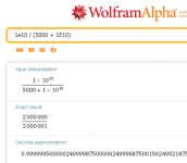
When looking at the curve in post #43 we see that diode leakage current is linearly proportional to applied voltage. Therefore the small signal incremental model of the diode is: a resistor! Again assuming a very cheap 1N3595 diode with 1nA of leakage, the resistance value of the small signal model is (10V / 1nA) = 1E10 ohms. Ten gigohms. This forms a voltage divider with your 5K output impedance, and Vout = Vin * (1E10/(5000+1E10)) = see below. Wrong by 0.5 parts per million.

_
Attachments
Last edited:
How so? If I have an opamp with, say, 60dB of open loop gain at the freq of interest, and 10V output, the effective input is 10mV, whatever the surrounding circuitry is, no?
Jan
I'm curious where exactly in an audio application would you be using op amps in open loop configuration.
Again assuming a very cheap 1N3595 diode with 1nA of leakage, the resistance value of the small signal model is (10V / 1nA) = 1E10 ohms. Ten gigohms. This forms a voltage divider with your 5K output impedance, and Vout = Vin * (1E10/(5000+1E10)) = see below. Wrong by 0.5 parts per million.
You're pessimistic. 😉 1nA is the leakage at Vreverse=125V.
If you want to clamp the output, go ahead, 1N3595 is a good choice. On the same line of price/performance there's also the FDH300.
I'm curious where exactly in an audio application would you be using op amps in open loop configuration.
I believe Jan is saying that IF "the frequency of interest" is 3 decades below the opamp's unity gain frequency, i.e., 60 dB of open loop gain above 0dB, then Vout/deltaVin = 60dB. Of course this makes the standard assumption of a single dominant pole above the unity gain frequency.
Last edited:
I'm curious where exactly in an audio application would you be using op amps in open loop configuration.
ANY opamp always operates open loop, from the perspective of the input signal. The feedback loop only manipulates the effective input signal as it subtracts it from the outside Vin.
So for a closed loop gain of say 5 times, and a Vout of 10V, the 'outside Vin' is 2V, and the feedback signal is 1.9999... depending on open loop gain. The point is that the opamp effective input voltage at the +in and -in pins is ALWAYS Vout/OL gain.
Jan
If the output impedance at the diode node is 5K ohms and if the diode leakage is a whopping 1000pA (1nA) with 10V of reverse bias, then the diode leakage introduces a voltage offset of 5 microvolts at the output. How much does that degrade your SNR? Fortunately, if yours is a strong output with an impedance lower than 5K, the voltage offset is lower too.
When looking at the curve in post #43 we see that diode leakage current is linearly proportional to applied voltage. Therefore the small signal incremental model of the diode is: a resistor! Again assuming a very cheap 1N3595 diode with 1nA of leakage, the resistance value of the small signal model is (10V / 1nA) = 1E10 ohms. Ten gigohms. This forms a voltage divider with your 5K output impedance, and Vout = Vin * (1E10/(5000+1E10)) = see below. Wrong by 0.5 parts per million.
_
Yeah maybe I worry too much 🙁
The linear-with-voltage leakage is a linear deviation, basically only modifying the gain but not causing distortion.
But how about non-linear junction capacitances?
Jan
ANY opamp always operates open loop, from the perspective of the input signal. The feedback loop only manipulates the effective input signal as it subtracts it from the outside Vin.
Replace "ANY" with "Ideal" and I might agree.
Otherwise I would have to remind you that in real life op amps do not have infinite input impedance.
And, depending of the particular internal schematic, they *will* manipulate the input signal, sometimes dramatically (witness this very interesting thread about input diodes).
Replace "ANY" with "Ideal" and I might agree.
No. ANY. Show me an example of an opamp where the signal at +in and -in is NOT Vout/OL gain.
It's pretty much the definition of open loop gain, no?
Edit: I realize we may have a misunderstanding here. I mean the actual open loop gain at that moment in a particular circuit, which is not necessarily the advertised OL gain in the data sheet.
jan
Last edited:
No. ANY. Show me an example of an opamp where the signal at +in and -in is NOT Vout/OL gain.
It's pretty much the definition of open loop gain, no?
jan
For starters, any opamp that has noise and offset. Which means all of them.
Last edited:
For starters, any opamp that has noise and offset. Which means all of them.
OK, if you want to go that way. The context was different. Well-known tactic.
Last edited:
- Status
- Not open for further replies.
- Home
- Amplifiers
- Solid State
- Back to back diodes at inputs of opamps