More or less. Technically it would be 'better' if the terminus was closer to the listener than the direct-radiating drive unit, as that will to an extent correct for some of the GD (providing you're on the right axis), but given the physical dimensions & other issues involved it's unlikely to be feasible for most home users.

One is a proper expanding horn with a flare factor, frequency, the other a stepped expanding horn, so not as smooth, efficient in theory, but have never done a comparison, so Scott would need to do sims for comparison.
That said, they're both parabolic flares since they each have a set of parallel sides, so not sure there would be much difference for a given acoustic pathlength except in the HF where it blends into the driver's output (baffle step) due to the slower expanding Olson flare.
Anyway, curious what Scott comes up with.
I'll try to post some comparative sims in a day or two, but I can't summarise any better than that. 😉
With my generalising hat on though, it's usually difficult to do exact comparisons because of the way the configurations tend to play out. Manifold (as I term it) construction is if nothing else very good at making efficient use of space in a given set of OA dimensions -with conventional angled baffles making up a more constant expansion you can sometimes find you end up needing slightly more.
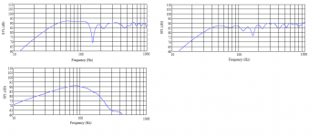
In general, I've found if you set the manifold proportions right for approximating a given [nominal] expansion profile (notwithstanding they're all strictly parabolic, as GM points out due to the parallel sides) then there's little in it in terms of efficiency, again assuming the same OA available cabinet dimensions. Since most are operating as resonant TLs for at least a portion of their BW, it's also usually six of one, half-a-dozen of the other as far as linearity goes, and as far as the LF is concerned, within reason it's dominated by how compromised the overall expansion is rather than the exact method of creating / approximating the expansion. Silbury is optimised as a corner design (also accounting for the rear integrating curve) and it's not too bad; I don't normally talk about them on the forum since they're a pay-for planset, but for what it's worth, a couple of sims attached -the measurements I've taken of test lines for this range are in good agreement assuming solid room construction. Top left is system response assuming corner loading, bottom the horn output. Right hand system graph shows results moved a reasonable distance away from the corner, but still with a reasonable front-wall boundary support (pulled out another few inches, 'just because') The null is the expected cancellation mode for the positioning used for these.
Anyway, will try to knock up some non-specific comparisons over the next few days. It's quite interesting. Well, I find it interesting.

Attachments
Last edited:
@Scottmoose we can talk about another design with straight panels, like this one.
https://e74a16cf-a-62cb3a1a-s-sites...ures/s8_TB-10F_01_single_back_loaded_horn.jpg
https://e74a16cf-a-62cb3a1a-s-sites...ures/s8_TB-10F_01_single_back_loaded_horn.jpg
It is the distance from the horn mouth to the ear. It needs to be in phase with the direct radiation.
In the 2n+1 figure, group delay increas with n.
dave
In the 2n+1 figure, group delay increas with n.
dave
Or in my simple minded children's 'soap bubble' toy ring way of viewing sound propagation through air is that a driver/horn/whatever terminus has a very fine membrane attached to it and when 'blown'/driven outward (compression/+) and inverted, its rarefaction (-) to complete 1 WL with the 'ring'/terminus area defining its fundamental.I read it as 'does the horn terminus have to be within a certain distance to the driver'.
From this we 'see' that way out at some small particle density we find its theoretical HF limit for a given medium and vice versa for its sub harmonic BW, so ideally we want subs much closer than the mains, but normally just use whichever polarity between the two sounds best in room when both are located on ~ the same horizontal/vertical plane and ideally within a 1/4 WL of its XO point, hence the 'driver in mouth'/whatever layout once any local boundaries, room acoustics in general are factored in.
 around this formula WRT a BLH's acoustic LPF, BSC design.

I confess that for back-horns, I simply use the -3dB point of the driver on-baffle, the effective mass-corner frequency, or (if either of those are still too high & I'm still obliged to use back-loading only), then the 250Hz - 300Hz BW accepting there will be a degree of gap, and assuming a/ a horn no longer than 7ft & preferably shorter if the terminus isn't coincident / in the same vertical plane as the driver, and b/ that I've got a reasonably steep / consistent acoustic low-pass.
Thanks, so using the approximation F(3) = (115 / baffle width in meters), to fit the 250 Hz BH frequency, the baffle should be at least 46 cm.I confess that for back-horns, I simply use the -3dB point of the driver on-baffle
Sorry for the newbie question, can I ask how to calculate it?the effective mass-corner frequency,
What could be a further implementation if not obliged to use back-loading only?or (if either of those are still too high & I'm still obliged to use back-loading only), then the 250Hz - 300Hz BW accepting there will be a degree of gap,
What are the benefits of a shorter horn compared to one longer than 2 meters?and assuming a/ a horn no longer than 7ft & preferably shorter if the terminus isn't coincident / in the same vertical plane as the driver
So I guess the Helmotz of the chamber plus one or more acoustic low-pass along the horn (EG a choked point, or folds)., and b/ that I've got a reasonably steep / consistent acoustic low-pass.
Thanks in advance,
Roberto
Not necessarily, approximations like the above assume you're dealing with a flat response which isn't always the case; you can have some units that have a naturally rising LF response that partly cancels out some of the losses; it also depends on the order of the acoustic low-pass; the slower it is, the more support you get, albeit that can end up increasing the audibility of GD so it's a balancing act as always, and really needs to be done on a case-by-case basis.Thanks, so using the approximation F(3) = (115 / baffle width in meters), to fit the 250 Hz BH frequency, the baffle should be at least 46 cm.
Fhm = 2Fs/Qts'Sorry for the newbie question, can I ask how to calculate it?
Where Fhm = nominal -3dB mass-corner frequency
Fs = driver resonant frequency, and
Qts' = effective Qts of the driver accounting for any series R in circuit, and / or the output impedance of the amplifier
Compound loading -short front midrange horn with a rear-loaded bass horn.What could be a further implementation if not obliged to use back-loading only?
I don't know if I'd call them 'benefits' -they are what they are and it depends on the type of design in question. A shorter horn in theory has less group delay from that factor (it's shorter) but it may be elevated through other causes -in general, you pick a load type for a given drive unit's characteristics, so you don't often end up in a situation where for a given target tuning (to keep variables under control) you can go one way or the other. Not always the case, especially if you're designing to request or for other people who have their own requirements / preferences, but that's the 'ideal'.What are the benefits of a shorter horn compared to one longer than 2 meters?
Thanks @Scottmoose ,
Can compound loading be applied to Silbury and FHXL designs?
I've always found front horns aestetically very appealing, but never heard any.
Can compound loading be applied to Silbury and FHXL designs?
I've always found front horns aestetically very appealing, but never heard any.
There's no requirement for it as they're already correctly balanced. All that adding a midrange horn would do is amplify that range excessively over the rest of the range. Compound horns are like anything else -you need to design them from scratch for them to be of value; it's not just a case of adding a midrange horn to an existing back-horn.
Adding to the F(3)=4560/width (inches), is an approximation based on Olson’s work on baffle roll-off.
Typically i have found the baffle step occurs at somewhere between 0.707-1 times that F(3)
dave
Typically i have found the baffle step occurs at somewhere between 0.707-1 times that F(3)
dave
- Home
- Loudspeakers
- Full Range
- Back loaded horn chamber role