[wiki=Main Page]return to diyAudio Wiki Main Page[/wiki]
[h=Introduction]%2[/h]
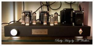
The Baby Huey PP ultra linear EL84 is a design by member Gingertube.
AFAIK there are 2 major versions. The first (auto bias), which is probably the one newbies should build and a fixed bias version. Below is the schematic of the auto bias.
From the first post by gingertube (edited):
This design is based upon an ECL86 Amp design posted by Yves Monmagnon quite some time ago. This design uses shunt feedback to reduce the output stage rp and thus better drive the limited primary inductance of cheaper output transformers. Regardless of that, the result is good enough that its worth using reasonable quality transformers and while the common Hammond 1608 (Raa = 8K) will work well, it really deserves something a bit higher quality (more expensive). It can be used without the Ultralinear connection BUT performance would be degraded.
It UNASHAMEDLY uses Solid State to assist the tubes toward their maximum performance.
I believe it is suitable as a "newbies" first project and it will certainly out-perform most of the simple "suitable for newbies" designs I have seen here and elsewhere.
In case I forgot - Thanks again to Yvesm for the original "damn clever" idea.
[h=Schematic]%2[/h]
Amp
 Compromised URL removed by Moderation
Auxiliary circuits
Compromised URL removed by Moderation
Psu
Compromised URL removed by Moderation
[h=So what is novel about this design?]%2[/h]
[h=ilimzn explains it very well I think:]%3[/h]
It is actually very simple, and elegant - and once you have figured it out, like most elegant designs, obvious
Consider this:
What would the voltage be on the joining point of the 47k and 220k resistors between the plates of the output and input LTP, IF the 16k resistor was a short circuit? Answer: it would be B+ reduced by the voltage drop of the OPT winding resistance, so close to B+. Why? Simple: because the amp is symmetrical PP, the OPT ends always swing symmetrically around +B, and making the 16k resistor a short, would just create a divider establishing a mean of the voltages on the output plates - which is exactly B+ lowered by the voltage drop in the OPT winding resistance. This establishes a virtual B+ for the LTP, and the impedance of the virtual B+ is 47k / 2.
Now, since the LTP has a CCS in the tail, the sum of both plate currents in it is always equal to the current through the CCS, i.e. a constant - this means there is a constant drop in the 47k/2 impedance of the virtual B+ - in essence, if the 16k resistor was a short, it becomes a 'common mode' node.
Finally, what happens now if the 16k resistor is NOT a short any more? Well, imagine it was made out of two equal resistors - 2x8k say, connected in series. Their center node remains the common mode point and is always at a voltage equal to the virtual B+ reduced by the drop in the 47k resistors. The big difference is now that the node between the 220k and 47k resistors is not the common mode node any more, but instead there is the AC component from the output tube plates, divided down by the 47k and half of the 16k resistor - i.e. there is feedback. The beauty of this is that changing the feedback can easily be made by the choice of the 16k resistor, without significantly changing the DC operating point of the LTP, because 47k in parallel with 1/2 of 16k is a rather small value compared to the 220k triode plate resistor, so DC currents branch just a little different and the virtual B+ remains almost the same.
One important point already made by the author: the input triodes are high Rp - and this is because the actual feedback is again scaled down by the divider formed from the 220k and the triode Rp. With a low Rp, feedback would always be low - and could only be increased by reducing the feedback network resistors, which means a higher current through the LTP and more losses for the output as this is where the current for the feedback network comes from. Alternatively, if a pentode LTP was used, then the high Rp of the pentodes would make the 220k resistor virtually insignificant in comparison, and feedback would not be scaled down.
[h=And here is gingertube's own explanation:]%3[/h]
For those wanting to understand the shunt feedback I offer the following opinion/best guesses and a few facts as to what is happening.
Aside: Newbies don't let the following "techno babble" put you off building one of these. You don't need to understand whats going on to build a great sounding "simple" amp. I believe that this is a fantastic choice as a first tube amplifier - the only thing wrong with it as a first amp is that its going to be VERY difficult for your second and third etc. amps to better.
There will be a virtual earth at the midpoint of the 16K which cross connects the two 47Ks from the anodes of the EL84s. (point with AC voltage = 0). This also somewhat divorces the AC and DC requirements of the diffamp and steps around one of the problems usually associated with shunt feedback using the diffamp anode loads returned directly to the output tube anodes.
The effective power to the diffamp sides therefore is the DC rail plus an AC feedback signal which is provided via an effective AC source impedance of about 8K. The virtual earth point will "shift" with any AC imbalance at the EL84 anodes and tend to correct that imbalance. This "self balancing" action is in addition to the "normal" shunt feedback action using up some of the EL84s gm to lower rp. That is: it does much the same as cathode feedback would do BUT with the additional AC balancing action. The lowered rp of the output tubes better drives moderate Lp of cheaper Output Transformers AND reflects to the secondary as lower amplifier output impedance and thus giving better damping and low frequency response. Similarly High frequency response will be improved by better drive of leakage inductance and shunt capacitance by the lower rp - a win - win - win situation.
Perhaps I should have called the amp "Serendipity" rather than "Baby Huey". Cetainly the tube choices and required operating points and the circuit topology and interactions just happen to all suit each other.
The circuit demands the correct tube choices. The Input (diffamp) devices must be low current and high rp which pretty well limits us to 12AX7ish tubes. The outputs must be high gm devices which will tolerate largish Rg1 values. That limits us to Cathode biased EL84 or if using fixed bias it needs a bias servo or similar to allow the use of that large Rg1. The original ECL86 triode and pentode sections provides both these things and works very well - unfortunately (to the best of my knowledge) ECL86 is not in current production. That was one of the reasons I decided to try the 12AX7 EL84 version (plus I had a Morgan Jones "Bervois Valley" amp which could be readily modified).
[h=Assorted info gathered from the original thread:]%2[/h]
BTW it was originally built with a single transistor current source on the diffamp. As with ALL single transistor current sources the AC impedance was limited by EARLY Effect. Changing the current source to a cascode gave immediately noticable improvement due to lifting the AC impedance by (probably) an order of magnitude.
As a practical exercise I have built a 6SL7 plus fixed biased 6V6G experimental version but low 6V6G Rg1 requirement (imposed by the fixed bias), lower 6V6 gm, higher currents for the 6SL7 etc. have meant that it just isn't in the same league - I keep running into limiting conditions everywhere as parametrers are pushed outside of acceptable limits - that is what I meant about SERENDIPITY with the 12AX7/EL84 version, in that case everything just ended up suiting everything else. This one is destined to have the shunt feedback deleted and cathode feedback from OT secondaries substituted instead. Even then I'm probably going to have to add MOSFET source followers to buffer the diffamp outputs into the 6V6s. It LOOKS stunning, just doesn't have sound to match - YET. Even so I don't believe it will ever match the ECC803S, EL84 version.
Other comments from my notes:
1) Wire the 100uF/0.22uF HV filters for each channel directly between the Output Transformer primary Centre Tap wire with the 0V returned to the same point as the EL84 bias block 0V connections. These are fed from the common HV Supply via individual 47R (currently 4R7) resistors to give (I hope) a bit of channel separtation. Of course if you have a couple of 100mA rated transformers it would be better to build as dual supplies, one for each channel. The HV secondaries need to be 240-0-240 or there abouts. It will work with HV between about 270V on the low side to 350 on the high side although with 350V DC I would perhaps up the EL84 screen resistors from 33R to say 270R (currently 150R)
2) If you don't have a separate 5V winding to generate the -12 to -13V supply for the diffamp CCS then use what ever low voltage winding you have. The voltage isn't critical - anywhere between about -7 and -30 would be OK. You may have to adjust the 1K6 and 1K values in the current source to keep LED current at around 2 to 5 mA.
3) The optional components the CCS are just a filter for any LED noise. I felt they made a very marginal improvement (but it might have been a case of "I expected to hear an improvement and therefore I did" which is a trap for young players to be aware of). The 22uF is a 22uF/6.3V Blackgate NX. If you are leaving them out the 470R needs to be replaced with a short circuit.
4) As a last resort if you have no other low voltage windings (which is what I ran into on my ECL86 version) you can just ditch the hetaer balance resistors (the 2 x 100R) and voltage double the 6.3 volt heater supplies. This will result in the heaters having about a -8V DC bias. I did'nt notice any detrimental effect (hum and noise) on the ECL86 version and you MAY get away with this in the 12AX7/EL84 version as well.
Component choices were what I had in my parts bins.
Components:
All the 0.22uF/400V are Wima FKP1 - I just bought a batch of them
The volume pot could be 50K log or 100K log rather than the 220K.
The MJE340s in the bias blocks don't need heatsinks if mounted against the chassis (they dissipate about 1/2 a watt) else a small heatsink would be advisable.
[h=Adjustments and pointers:]%2[/h]
Set the BAL.(ance) pot for equal anode voltages at pins 1 and 6 of the ECC803S (premium 12AX7)
The 16K resistor between the 47Ks from the EL84 Anodes sets the shunt feedback level. Too much and the input stage will clip and output power will reduce.
The 12K and 470R network in the grid circuit (pin 1 of ECC803S) set the global feedback. I've used minimal global feedback.
Those 47R 2W in the original schematic were subsequently dropped to 4R7.
Its not a great idea to waste heat and power in dropping resistors in the main HT supplies.
Ideal Voltage is about +320V. You really don't want to go above say +350V and even then I would change the 16 Ohm resistors in the EL84 cathode current sources to 18 Ohm to knock the idle current back from 38mA per tube to about 34 mA so as to keep total dissipation in the EL84s to around 12 watts.
Choke Input is a really good way to go as you can fine tune the final output voltage with a 0.5 to 2uF cap straight off the rectifier and before the choke. PSUD2 models this behaviour quite well. If you have seriously too much voltage you may like to even think about a tube rectifier although it may look a bit weird with a thumping great rectifier tube adjacent those little 9 pin tubes. 5AR4 would be the go.
The tube rectified version with separate chokes feeding each channel perhaps sounds maybe 1% better.
Grid stoppers
Put the grid stopper resistors as close to the tube pins as possible. (1k resistors attached to pin 2 and 7 of the ECC803S and 4k7 resistors attached to pin 2 of the EL84.
[h=A little about the value of the cross-coupled resistor: R3]%2[/h]
With the cross coupled shunt feedback resistor in the 16K to 22K range it does indeed sound very Single Ended Triode-ish. With that resistor pushed up to 47K it cleans up a little more with some added detail but starts to sound more, dare I say it, Solid State -ish (anyway a bit "dry"). I think this gets back to balancing the 2H vs 3H harmonic content rather than trying to squeeze out the lowest possible harmonic distortion level which I'm increasingly convinced is the key to gorgeousness and "emotional content" in the music.
Anyway everyone can "tune" this shunt feedback set resistor to their own personal preference and speakers. I think mine is going to be at around 27K or 33K BUT that is with my nominally 6 Ohm VAF DCX Speakers.
[h=Removing global feedback: R1]%2[/h]
Remove resistor R1. This is a matter of taste. Alternatively you can change the value. Increase the value to decrease the amount of feedback. Or even add a potentiometer to tweak for various types of music. If you do use global feedback. The negative from the output transformers MUST be connected to ground.
[h=3rd harmonic distortion suppression scheme]%2[/h]
This has been popularized by Allen Wright as far as I know. Not sure who invented it.
Each Output tube current source has a bypass capacitor. Disconnect the -ve (0V) ends of these bypass capacitors but leave them joined together. Then add a single 33 Ohm between the bypass capacitors -ve terminals and the old 0V connection point.
(I used 33 because I had it in my parts bin. Gingertube uses a 39 Ohm. Either value will do.)
The added resistor is shown in pic below:
Compromised URL removed by Moderation
[h=Alternative bias blocks]%2[/h]
Here is an alternative bias block. Chosen because of what some may have lying in their parts bin. More to come.
[wiki=DN2450 based CCS (used as sink (bias block)) for an output tube.]%[/wiki]
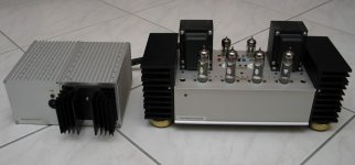
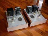
[h=Baby Huey as power amplifier with balanced input]%2[/h]
Compromised URL removed by Moderation
[h=Baby Huey without global feedback]%2[/h]
Compromised URL removed by Moderation
Schematic drawings kindly provided by TAJ (forum member diyAudio.com)
Links:
The original thread
EL84/6BQ5 wiki diyAudio)
My Baby Huey build in progress
[h=Introduction]%2[/h]
The Baby Huey PP ultra linear EL84 is a design by member Gingertube.
AFAIK there are 2 major versions. The first (auto bias), which is probably the one newbies should build and a fixed bias version. Below is the schematic of the auto bias.
From the first post by gingertube (edited):
This design is based upon an ECL86 Amp design posted by Yves Monmagnon quite some time ago. This design uses shunt feedback to reduce the output stage rp and thus better drive the limited primary inductance of cheaper output transformers. Regardless of that, the result is good enough that its worth using reasonable quality transformers and while the common Hammond 1608 (Raa = 8K) will work well, it really deserves something a bit higher quality (more expensive). It can be used without the Ultralinear connection BUT performance would be degraded.
It UNASHAMEDLY uses Solid State to assist the tubes toward their maximum performance.
I believe it is suitable as a "newbies" first project and it will certainly out-perform most of the simple "suitable for newbies" designs I have seen here and elsewhere.
In case I forgot - Thanks again to Yvesm for the original "damn clever" idea.
[h=Schematic]%2[/h]
Amp
Compromised URL removed by ModerationAuxiliary circuits
Compromised URL removed by ModerationPsu
Compromised URL removed by Moderation[h=So what is novel about this design?]%2[/h]
[h=ilimzn explains it very well I think:]%3[/h]
It is actually very simple, and elegant - and once you have figured it out, like most elegant designs, obvious
Consider this:
What would the voltage be on the joining point of the 47k and 220k resistors between the plates of the output and input LTP, IF the 16k resistor was a short circuit? Answer: it would be B+ reduced by the voltage drop of the OPT winding resistance, so close to B+. Why? Simple: because the amp is symmetrical PP, the OPT ends always swing symmetrically around +B, and making the 16k resistor a short, would just create a divider establishing a mean of the voltages on the output plates - which is exactly B+ lowered by the voltage drop in the OPT winding resistance. This establishes a virtual B+ for the LTP, and the impedance of the virtual B+ is 47k / 2.
Now, since the LTP has a CCS in the tail, the sum of both plate currents in it is always equal to the current through the CCS, i.e. a constant - this means there is a constant drop in the 47k/2 impedance of the virtual B+ - in essence, if the 16k resistor was a short, it becomes a 'common mode' node.
Finally, what happens now if the 16k resistor is NOT a short any more? Well, imagine it was made out of two equal resistors - 2x8k say, connected in series. Their center node remains the common mode point and is always at a voltage equal to the virtual B+ reduced by the drop in the 47k resistors. The big difference is now that the node between the 220k and 47k resistors is not the common mode node any more, but instead there is the AC component from the output tube plates, divided down by the 47k and half of the 16k resistor - i.e. there is feedback. The beauty of this is that changing the feedback can easily be made by the choice of the 16k resistor, without significantly changing the DC operating point of the LTP, because 47k in parallel with 1/2 of 16k is a rather small value compared to the 220k triode plate resistor, so DC currents branch just a little different and the virtual B+ remains almost the same.
One important point already made by the author: the input triodes are high Rp - and this is because the actual feedback is again scaled down by the divider formed from the 220k and the triode Rp. With a low Rp, feedback would always be low - and could only be increased by reducing the feedback network resistors, which means a higher current through the LTP and more losses for the output as this is where the current for the feedback network comes from. Alternatively, if a pentode LTP was used, then the high Rp of the pentodes would make the 220k resistor virtually insignificant in comparison, and feedback would not be scaled down.
[h=And here is gingertube's own explanation:]%3[/h]
For those wanting to understand the shunt feedback I offer the following opinion/best guesses and a few facts as to what is happening.
Aside: Newbies don't let the following "techno babble" put you off building one of these. You don't need to understand whats going on to build a great sounding "simple" amp. I believe that this is a fantastic choice as a first tube amplifier - the only thing wrong with it as a first amp is that its going to be VERY difficult for your second and third etc. amps to better.
There will be a virtual earth at the midpoint of the 16K which cross connects the two 47Ks from the anodes of the EL84s. (point with AC voltage = 0). This also somewhat divorces the AC and DC requirements of the diffamp and steps around one of the problems usually associated with shunt feedback using the diffamp anode loads returned directly to the output tube anodes.
The effective power to the diffamp sides therefore is the DC rail plus an AC feedback signal which is provided via an effective AC source impedance of about 8K. The virtual earth point will "shift" with any AC imbalance at the EL84 anodes and tend to correct that imbalance. This "self balancing" action is in addition to the "normal" shunt feedback action using up some of the EL84s gm to lower rp. That is: it does much the same as cathode feedback would do BUT with the additional AC balancing action. The lowered rp of the output tubes better drives moderate Lp of cheaper Output Transformers AND reflects to the secondary as lower amplifier output impedance and thus giving better damping and low frequency response. Similarly High frequency response will be improved by better drive of leakage inductance and shunt capacitance by the lower rp - a win - win - win situation.
Perhaps I should have called the amp "Serendipity" rather than "Baby Huey". Cetainly the tube choices and required operating points and the circuit topology and interactions just happen to all suit each other.
The circuit demands the correct tube choices. The Input (diffamp) devices must be low current and high rp which pretty well limits us to 12AX7ish tubes. The outputs must be high gm devices which will tolerate largish Rg1 values. That limits us to Cathode biased EL84 or if using fixed bias it needs a bias servo or similar to allow the use of that large Rg1. The original ECL86 triode and pentode sections provides both these things and works very well - unfortunately (to the best of my knowledge) ECL86 is not in current production. That was one of the reasons I decided to try the 12AX7 EL84 version (plus I had a Morgan Jones "Bervois Valley" amp which could be readily modified).
[h=Assorted info gathered from the original thread:]%2[/h]
BTW it was originally built with a single transistor current source on the diffamp. As with ALL single transistor current sources the AC impedance was limited by EARLY Effect. Changing the current source to a cascode gave immediately noticable improvement due to lifting the AC impedance by (probably) an order of magnitude.
As a practical exercise I have built a 6SL7 plus fixed biased 6V6G experimental version but low 6V6G Rg1 requirement (imposed by the fixed bias), lower 6V6 gm, higher currents for the 6SL7 etc. have meant that it just isn't in the same league - I keep running into limiting conditions everywhere as parametrers are pushed outside of acceptable limits - that is what I meant about SERENDIPITY with the 12AX7/EL84 version, in that case everything just ended up suiting everything else. This one is destined to have the shunt feedback deleted and cathode feedback from OT secondaries substituted instead. Even then I'm probably going to have to add MOSFET source followers to buffer the diffamp outputs into the 6V6s. It LOOKS stunning, just doesn't have sound to match - YET. Even so I don't believe it will ever match the ECC803S, EL84 version.
Other comments from my notes:
1) Wire the 100uF/0.22uF HV filters for each channel directly between the Output Transformer primary Centre Tap wire with the 0V returned to the same point as the EL84 bias block 0V connections. These are fed from the common HV Supply via individual 47R (currently 4R7) resistors to give (I hope) a bit of channel separtation. Of course if you have a couple of 100mA rated transformers it would be better to build as dual supplies, one for each channel. The HV secondaries need to be 240-0-240 or there abouts. It will work with HV between about 270V on the low side to 350 on the high side although with 350V DC I would perhaps up the EL84 screen resistors from 33R to say 270R (currently 150R)
2) If you don't have a separate 5V winding to generate the -12 to -13V supply for the diffamp CCS then use what ever low voltage winding you have. The voltage isn't critical - anywhere between about -7 and -30 would be OK. You may have to adjust the 1K6 and 1K values in the current source to keep LED current at around 2 to 5 mA.
3) The optional components the CCS are just a filter for any LED noise. I felt they made a very marginal improvement (but it might have been a case of "I expected to hear an improvement and therefore I did" which is a trap for young players to be aware of). The 22uF is a 22uF/6.3V Blackgate NX. If you are leaving them out the 470R needs to be replaced with a short circuit.
4) As a last resort if you have no other low voltage windings (which is what I ran into on my ECL86 version) you can just ditch the hetaer balance resistors (the 2 x 100R) and voltage double the 6.3 volt heater supplies. This will result in the heaters having about a -8V DC bias. I did'nt notice any detrimental effect (hum and noise) on the ECL86 version and you MAY get away with this in the 12AX7/EL84 version as well.
Component choices were what I had in my parts bins.
Components:
All the 0.22uF/400V are Wima FKP1 - I just bought a batch of them
The volume pot could be 50K log or 100K log rather than the 220K.
The MJE340s in the bias blocks don't need heatsinks if mounted against the chassis (they dissipate about 1/2 a watt) else a small heatsink would be advisable.
[h=Adjustments and pointers:]%2[/h]
Set the BAL.(ance) pot for equal anode voltages at pins 1 and 6 of the ECC803S (premium 12AX7)
The 16K resistor between the 47Ks from the EL84 Anodes sets the shunt feedback level. Too much and the input stage will clip and output power will reduce.
The 12K and 470R network in the grid circuit (pin 1 of ECC803S) set the global feedback. I've used minimal global feedback.
Those 47R 2W in the original schematic were subsequently dropped to 4R7.
Its not a great idea to waste heat and power in dropping resistors in the main HT supplies.
Ideal Voltage is about +320V. You really don't want to go above say +350V and even then I would change the 16 Ohm resistors in the EL84 cathode current sources to 18 Ohm to knock the idle current back from 38mA per tube to about 34 mA so as to keep total dissipation in the EL84s to around 12 watts.
Choke Input is a really good way to go as you can fine tune the final output voltage with a 0.5 to 2uF cap straight off the rectifier and before the choke. PSUD2 models this behaviour quite well. If you have seriously too much voltage you may like to even think about a tube rectifier although it may look a bit weird with a thumping great rectifier tube adjacent those little 9 pin tubes. 5AR4 would be the go.
The tube rectified version with separate chokes feeding each channel perhaps sounds maybe 1% better.
Grid stoppers
Put the grid stopper resistors as close to the tube pins as possible. (1k resistors attached to pin 2 and 7 of the ECC803S and 4k7 resistors attached to pin 2 of the EL84.
[h=A little about the value of the cross-coupled resistor: R3]%2[/h]
With the cross coupled shunt feedback resistor in the 16K to 22K range it does indeed sound very Single Ended Triode-ish. With that resistor pushed up to 47K it cleans up a little more with some added detail but starts to sound more, dare I say it, Solid State -ish (anyway a bit "dry"). I think this gets back to balancing the 2H vs 3H harmonic content rather than trying to squeeze out the lowest possible harmonic distortion level which I'm increasingly convinced is the key to gorgeousness and "emotional content" in the music.
Anyway everyone can "tune" this shunt feedback set resistor to their own personal preference and speakers. I think mine is going to be at around 27K or 33K BUT that is with my nominally 6 Ohm VAF DCX Speakers.
[h=Removing global feedback: R1]%2[/h]
Remove resistor R1. This is a matter of taste. Alternatively you can change the value. Increase the value to decrease the amount of feedback. Or even add a potentiometer to tweak for various types of music. If you do use global feedback. The negative from the output transformers MUST be connected to ground.
[h=3rd harmonic distortion suppression scheme]%2[/h]
This has been popularized by Allen Wright as far as I know. Not sure who invented it.
Each Output tube current source has a bypass capacitor. Disconnect the -ve (0V) ends of these bypass capacitors but leave them joined together. Then add a single 33 Ohm between the bypass capacitors -ve terminals and the old 0V connection point.
(I used 33 because I had it in my parts bin. Gingertube uses a 39 Ohm. Either value will do.)
The added resistor is shown in pic below:
Compromised URL removed by Moderation[h=Alternative bias blocks]%2[/h]
Here is an alternative bias block. Chosen because of what some may have lying in their parts bin. More to come.
[wiki=DN2450 based CCS (used as sink (bias block)) for an output tube.]%[/wiki]
[h=Baby Huey as power amplifier with balanced input]%2[/h]
Compromised URL removed by Moderation[h=Baby Huey without global feedback]%2[/h]
Compromised URL removed by ModerationSchematic drawings kindly provided by TAJ (forum member diyAudio.com)
Links:
The original thread
EL84/6BQ5 wiki diyAudio)
My Baby Huey build in progress
Attachments
-
 babyhueyfinalpx0.jpg80.6 KB · Views: 2,274
 -
 20080211_0580-2.jpg89.6 KB · Views: 2,060
 -
 jombbhview1.jpg53.4 KB · Views: 1,947
 -
 huey1.JPG93.5 KB · Views: 855
 -
 3rdharm.gif20.5 KB · Views: 1,115
 -
 BH.jpg91.3 KB · Views: 675
 -
 bhoutsidemed.jpg28.6 KB · Views: 494
 -
 bhmonoblock.jpg100.9 KB · Views: 513
 -
 IMG_1033.JPG108.5 KB · Views: 446
 -
 IMG_1026.JPG142.2 KB · Views: 784
Last edited by a moderator: