I built the PCB based Baby Huey in both EL84 and EL34 variants, as described in this forum by gingertube and bandol83, but I have admired the original version of the amplifier, created by Yves from Dissident Audio ...
ECL86 P-P
The design is very elegant.
Marc, aka bandol83 on this site, also appreciated the design, and adapted the design for a UL OPT, with some other minor changes. I decided to build that version, using transformers from AskJanFirst.
I am struggling a bit to get it going properly. Part of the problem is that I have repurposed a power transformer I already had, and this is 109-0-109 CT which I am using without the CT, so 218 VAC which should be the right B+. There is also a 8-0-8 VAC winding, 1.6A, which just about provides the 4 x 6.3v 0.725A heater requirements, with a dropping resistor as well. I also added a 6VAC PCB mounted transformer, with a quadrupler and zener with serial resistance for the -20VDC rail. That all seems to be OK, but adds a bit of risk to the implementation.
It was my intention to model the design in LTSpice so that I could compare the theoretical performance of the amp against my measurements. Unfortunately I cannot get the model to work very well, so was hoping someone here could point out what I have missed in the LTSpice model. The schematic I am using is here ...

The model and tube library files are attached.
Has anyone built this variant? I put the CCS on some experiment board, but I wasn't sure how to test it in isolation. I am getting some odd voltages on the tube pins, so would really like to get the model working so I can get confidence in the design, and use that to debug the amp I built. After initial testing I can already see I wired the volume pot back to front, so volume goes down as you turn the pot clockwise, but I don't think that would prevent the amp working.
ECL86 P-P
The design is very elegant.
Marc, aka bandol83 on this site, also appreciated the design, and adapted the design for a UL OPT, with some other minor changes. I decided to build that version, using transformers from AskJanFirst.
I am struggling a bit to get it going properly. Part of the problem is that I have repurposed a power transformer I already had, and this is 109-0-109 CT which I am using without the CT, so 218 VAC which should be the right B+. There is also a 8-0-8 VAC winding, 1.6A, which just about provides the 4 x 6.3v 0.725A heater requirements, with a dropping resistor as well. I also added a 6VAC PCB mounted transformer, with a quadrupler and zener with serial resistance for the -20VDC rail. That all seems to be OK, but adds a bit of risk to the implementation.
It was my intention to model the design in LTSpice so that I could compare the theoretical performance of the amp against my measurements. Unfortunately I cannot get the model to work very well, so was hoping someone here could point out what I have missed in the LTSpice model. The schematic I am using is here ...
The model and tube library files are attached.
Has anyone built this variant? I put the CCS on some experiment board, but I wasn't sure how to test it in isolation. I am getting some odd voltages on the tube pins, so would really like to get the model working so I can get confidence in the design, and use that to debug the amp I built. After initial testing I can already see I wired the volume pot back to front, so volume goes down as you turn the pot clockwise, but I don't think that would prevent the amp working.
Attachments
I can't help you with LTSpice. But I noticed a couple of things in the original schematic you linked to:
The voltage drop over R4 is indicated as 100 V, so the current through R4 would be 0.45 mA. But this doesn't match with the indicated cathode current of 0.5 mA per triode section.
The voltage drop over R5 is indicated as 15 V, so the current through R5 would be 0.32 mA. But this doesn't match the calculated 0.45 mA through R4.
The anode voltage of the pentode sections is indicated as 245 V. But B+ is also indicated as 245 V. I would think one of them must be wrong since there will be some voltage drop over the dc-resistance of half of the primary of the OPT.
Vak is indicated in the notes as being 242 V, so 3 V lower than 245 V. But if B+ is indeed 245 V, and (because of the voltage drop in the primary of the OPT) the anode voltage of the pentode sections is indeed 242 V, than the current through R5 would only be 0.26 mA, so even more off of the calulated current of 0.45 mA through R4.
The Ayumi tube parameter model you are using defines only 4 electrodes - tetrode, not 5 - pentode.It was my intention to model the design in LTSpice so that I could compare the theoretical performance of the amp against my measurements. Unfortunately I cannot get the model to work very well, so was hoping someone here could point out what I have missed in the LTSpice model.
Most tube models do that.
Which means you have to replace the pentode in your .asc file with a tetrode assembly.
Done that, renamed the .txt model files to .sub, replaced the undefined LED with a RED LED from the LTspice library and it worked.
See corrected file attached.
Attachments
I have it built at long last, and it does sound very nice. I have two remaining niggles.
1) The gain is around 7, so 3.5V RMS out from a 0.5V RMS source. Does that seem a bit low? It works in my setup, but I am hoping to pass it onto my sone, so I am preempting any criticisms I might get later ;-)
The gain is in line with what the simulation tells me.
Has anyone built this who can comment? My B+ has ended up 270Vdc, so with 10V on the cathode that is 260V across the pentode, and Rk is 470R, so that is only 21mA for each tube, or 5.5W, well within the limit of 9W. Maybe a lower Rk value is an option, or should I just enjoy it ;-) I am mindful that this is not the most straightforward design, with a lot of interoperation of differen tparts, so I don't really want to tinker too much.
2) I wanted to use some parts I had knocking around, and I had this transformer which delivers the right B+, but has an odd LT winding of 8-0-8 1.6A. I will be able to use PCL86 or ECL86 with that, so that is a positive thing, but both require dropping resistors to get the voltage right. Currently I have some Tungsram ECL86 in there, with 4x0.33R 5W in series on each pair of ECL86s. So that is 2 x (1.7v @ 1.4A) that is being dissipatated by those resistors, which is close to 5W total. That is a bit of heat over time under the chassis.
I was thinking to add a bridge rectifier, to drop 2 x 0.6V in the rectifier, and I calculated with PSUD2 that a CRC of 4700uf + 1.1R + 4700uf should get me in the ballpark. I have not tried DC heaters so far - is this a worthwhile solution?
The power switch will be replaced - the one I had on there was intermittent so had to be binned.
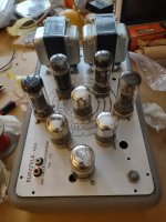
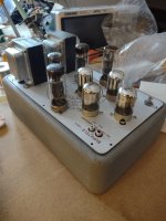
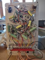
The metal box was an old Euratele signal generator, but it has been a 3D puzzle to get everthing in there, partly because the transformers had to be dropped through rather than bolted on top because that was not possible (they are from Ask Jan First). I built it on an aluminium sub-chassis, which is a trick I will do again since it meant I did not need exposed screws on the top plate aprat from two to hold the subchassis in place.


1) The gain is around 7, so 3.5V RMS out from a 0.5V RMS source. Does that seem a bit low? It works in my setup, but I am hoping to pass it onto my sone, so I am preempting any criticisms I might get later ;-)
The gain is in line with what the simulation tells me.
Has anyone built this who can comment? My B+ has ended up 270Vdc, so with 10V on the cathode that is 260V across the pentode, and Rk is 470R, so that is only 21mA for each tube, or 5.5W, well within the limit of 9W. Maybe a lower Rk value is an option, or should I just enjoy it ;-) I am mindful that this is not the most straightforward design, with a lot of interoperation of differen tparts, so I don't really want to tinker too much.
2) I wanted to use some parts I had knocking around, and I had this transformer which delivers the right B+, but has an odd LT winding of 8-0-8 1.6A. I will be able to use PCL86 or ECL86 with that, so that is a positive thing, but both require dropping resistors to get the voltage right. Currently I have some Tungsram ECL86 in there, with 4x0.33R 5W in series on each pair of ECL86s. So that is 2 x (1.7v @ 1.4A) that is being dissipatated by those resistors, which is close to 5W total. That is a bit of heat over time under the chassis.
I was thinking to add a bridge rectifier, to drop 2 x 0.6V in the rectifier, and I calculated with PSUD2 that a CRC of 4700uf + 1.1R + 4700uf should get me in the ballpark. I have not tried DC heaters so far - is this a worthwhile solution?
The power switch will be replaced - the one I had on there was intermittent so had to be binned.
The metal box was an old Euratele signal generator, but it has been a 3D puzzle to get everthing in there, partly because the transformers had to be dropped through rather than bolted on top because that was not possible (they are from Ask Jan First). I built it on an aluminium sub-chassis, which is a trick I will do again since it meant I did not need exposed screws on the top plate aprat from two to hold the subchassis in place.
Last edited:
The design is very elegant.
Marc, aka bandol83 on this site, also appreciated the design, and adapted the design for a UL OPT, with some other minor changes. I decided to build that version, using transformers from AskJanFirst.
@OldHector,
I’m thinking of building your adaptation of Yves’ elegant design with PCL86 tubes. Are you still happy with it? How does it‘s performance compared with your Tubelabs SPP style EL86 amplifier?
Which transformer of AskJanFirst did you use. (Sorry if I missed it in the posts). Would you use it again if you were to repeat the build? I have a pair of Toroidy TTG-ECL86 UL (40%) transformers with 10k primary. Should I get Jan’s transformers?
Hi @Francois G ,
Yes, still happy with the amplifier.
Recently I bought a cheap 300B amplifier from a bit of a remote location for less money than the sum of the parts (Lundahl transformers, silver caps, PSVANE gold tubes), but it could not compete for the quality of the sound from the little BH ECL86 amp! There is a real purity in the sound that I appreciate. The bass from the little OPTs is perfectly fine, and the amplifier is a great companion for working from home, with YouTube and a Bluetooth receiver.
The OPTs from Ask Jan were ATRA0427 and the choke was D10-200. The power traffo was something that I had lying around that had an odd 8-0-8VDC secondary, which was adapted to be either 2 pairs of 6.3V heaters in parallel or 4 x 13.3V in parallel, with suitable dropping resistors.
The OPT transformers are made in a way that prevented a bell end cover from being fitted on both sides, so I had to drop them through the top of the amplifier, and I had to rethink the whole construction at that point, ending up building it with the box upside down. That forced me to build on a sub-chassis which I would do again. It was a bit like having a PCB.
I think your Toroidy OPTs will be better performing than the Ask Jan ones. I deliberately wanted a cheaper build, and they were about €100 for the pair. I doubt if they would beat the top part of the output range, but bass is most likely going to be extended a bit.
At some point I'd like to try a variant with loctal tubes, 7B6 as the triode and EBL21 as the output tube. Looks to have similar characteristics on paper.
Great information! Thanks @OldHector. Good luck with the future loctal version.
@OldHector have you tried both the 40%UL version and the pentode version?
Thanks
Thanks
It can be interesting to apply something similar to the EL34 version.
By using the EL34 in pentode mode we get the two advantages of having a lower capacitance on g1 and less swing needed to reach full power, so less current on the phase splitter can still give good results. I think something around 460V B+, 350V g2 and 6k6 should be fine staying above -30V bias.
By using the EL34 in pentode mode we get the two advantages of having a lower capacitance on g1 and less swing needed to reach full power, so less current on the phase splitter can still give good results. I think something around 460V B+, 350V g2 and 6k6 should be fine staying above -30V bias.
@OldHector: I'm aware that my thoughts are a bit late, but your thread didn't pop up earlier for me ") ...
...
Let's start: Why did you provide DC balancing in your LTP? The CCS as the tail in connection with equal plate resistances ensures perfect AC signal balancing at the plates. DC balancing isn't necessary. Then, what else than dramatically decreasing gain does resistor R8 do? Most probably this resistor is the reason of the small gain you were complaining in #5. Finally, it doesn't matter what you provide to dissipate the superfluous heater voltage. You'll generate exactly the same heat, no matter by which means.
Best regards!
Edit: After some re-thinking I guess i can't hold my complaints about R8. Sorry!
...Let's start: Why did you provide DC balancing in your LTP? The CCS as the tail in connection with equal plate resistances ensures perfect AC signal balancing at the plates. DC balancing isn't necessary. Then, what else than dramatically decreasing gain does resistor R8 do? Most probably this resistor is the reason of the small gain you were complaining in #5. Finally, it doesn't matter what you provide to dissipate the superfluous heater voltage. You'll generate exactly the same heat, no matter by which means.
Best regards!
Edit: After some re-thinking I guess i can't hold my complaints about R8. Sorry!
Last edited:
Hi Kay, as mentioned in the first message on the thread, I had looked at the Yves original, and compared it with the copy that Marc (bandol83) made.
There is some discussion about those changes here:
Troisieme CG pour Push-Pull ECL86 Dissident Audio.
So, it looks like the balancing is not required, as you say. However the next iteration from Gingertube kept the arrangement, so I decided to go with the flow.
BH EL84
R8 is a critical element of the BH sound and has been discussed in different threads.
Gingertube explains it HERE
Also some comments from John Steward and Chris Hornbeck on this thread, which had been discussing Schade feedback ...
Simple ECL86 Amp
Maybe the balancing is required to shift the virtual ground point for the output stage?
Cheers Richard
Hi Zintolo, the amplifier was built as an antidote to working in a locked down world, where I had to be in another country due to data security reasons, and worked for 15 months in a single room without going to the office, or hardly even meeting anyone come to that. I built it over a couple of months according to the recipe, and the OPTs I had bought were not so pretty, or so easy to wire actually (two of the wires were just loose small gauge enameled wire connections).have you tried both the 40%UL version and the pentode version?
The complexity was getting it to fit in the box, and the power supply for the CCS plus adapting the donor power transformer. Apart from some hole punches, I only had a hacksaw blade and files, so the bulk of the effort was drilling, sawing and filing, without alerting the Swiss authorities to my attempt to escape the country ;-/
I recently bought a couple of pentode mode only Sowter OPTs on an auction site, with 8k primary impedance, and I have this hope to build a loctal only version, so I will see how that pans out. Yves' original was pentode mode, and in the link I posted above he was not a fan of the UL solution.
Cheers Richard
Thanks Richard!
Indeed that was the reason of the question: Yves preferred the pentode version, Ian preferred the 40% UL version.
I've done some tests with this configuration and I prefer 20-25%UL: it gives the PSU simplicity of the UL, it still contributes to lower the Zout while giving almost pentode-like power.
Yesterday evening I've tried to sketch an EL34 pentode with Shade feedback, 460V B+, 320 V g2, -24V g1, 7k Raa, but it has a Zout around 7 Ohm (DF around 1.1). With a 33k 27k 33k shade feedback resistor set, and 180k on phase splitter plates I can reach 1 mA on the phase splitter.
This, together with the high gain due to the pentode mode, should give good slew-rate results without having a powerdriver, and full power with something like 1,1 Vrms at its input.
Some error-only feedback is needed to reach a better DF without affecting the sensitivity of the amp.
I've done some tests with my BHEL34 that is a bit modified compared to the original one:
I've understood why Yves used a lower feedback resistor R8 (that means less feedback in this configuration) plus some gnfb:
R8 is set just to triodize the curves without reducing the phase splitter gain, while the Rout is set to an acceptable level by using a flattish 8-10k loadline and the gnfb.
I've tested my amp with screens at 350V, local feedback as 33k 10k 33k, plus error-only gnfb: it is fine.
They sensitivity is of course higher, and the DF can be set higher as well. Good on some speakers, bad on others, and I was listening through a pair of full range, not the best choice for high DF amps. I will give more time on them, then I will try through my Klipsch.
- B+ is 460V
- UL is 23% instead of 40%
- Raa is 6.6k instead of 4.3k
- Phase splitter plate resistors are 270k instead of 220k to target a similar BHEL84 working point with more current (due to the higher needed swing) and higher B+
- Same feedback values (47k 39k 47k) but here has a stronger effect because the EL34 plate swing is higher than in the original one
- Switchable in/out error-only feedback
I've understood why Yves used a lower feedback resistor R8 (that means less feedback in this configuration) plus some gnfb:
R8 is set just to triodize the curves without reducing the phase splitter gain, while the Rout is set to an acceptable level by using a flattish 8-10k loadline and the gnfb.
I've tested my amp with screens at 350V, local feedback as 33k 10k 33k, plus error-only gnfb: it is fine.
They sensitivity is of course higher, and the DF can be set higher as well. Good on some speakers, bad on others, and I was listening through a pair of full range, not the best choice for high DF amps. I will give more time on them, then I will try through my Klipsch.
Hi @zintolo,
I think this is interesting but I’m not sure I understand fully.
Could you please unpack for us slower folks: “R8 is set just to triodize the curves without reducing the phase splitter gain, while the Rout is set to an acceptable level by using a flattish 8-10k loadline and the gnfb.”
I think this is interesting but I’m not sure I understand fully.
Could you please unpack for us slower folks: “R8 is set just to triodize the curves without reducing the phase splitter gain, while the Rout is set to an acceptable level by using a flattish 8-10k loadline and the gnfb.”
Sure @Francois G @OldHector !
R6+R7+R8 are what we call the Shade feedback.
The higher R8, the higher the isolation between the two sides of the phase splitter plates, the higher the swing on each node R6-R8 and R7-R8, the lower the load of the phase splitter, the higher the shunt feedback, the lower rp.
To simplify: Shade feedback trades gm for rp: the higher R8, the steeper triode-like the curves.
Yves decided to apply two feedbacks: a light a-g1 through Shade feedback just to have triodish curves (not very steep) and global negative feedback (to increase the DF of the amp and reduce distortion). One local and one global feedback.
Ian decided to apply two feedbacks as well, but different ones: a quite strong 40% a-g2 through UL and a strong a-g1 though Shade feedback.
So both local feedback.
A loadline around 8-10k permits to have a good DF without having a very low rp (because it's just the ratio of the two).
On top of that, that kind of load gives very low THD on triode curves, even if power will be lower.
What I tried and want to check with more time and an improved design, is going back to Yves roots (small amount of Shade feedback), but with error-only gnfb instead of conventional gnfb.
On LTSpice I can get around 80Wrms at 1% THD from a pair of KT88 and a 12AX7 as a phase splitter, with a DF of 22 and just 1.2 Vrms at its input.
Progress, but not sure if it will fly yet.At some point I'd like to try a variant with loctal tubes, 7B6 as the triode and EBL21 as the output tube. Looks to have similar characteristics on paper.
Attachments
Why shouldn't it? The 7B6 triode is almost the same as a 12AX7 or a ECL86/6GW8 triode, and the EBL21 pentode doesn't differ that much from any European 9 watts pentode since AL4. It's a 11 watt pentode, though, but electrically equivalent to it's predecessor, the EBL1, which in turn was a 9 watt plate dissipation pentode.
Did you acquire the EBL21's for little money?
Best regards!
Did you acquire the EBL21's for little money?
Best regards!
- Home
- Amplifiers
- Tubes / Valves
- Baby Huey ECL86/Dissident Audio