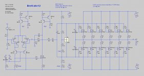
Suppose one had a BA2-like beast with separate FE and OS supplies:

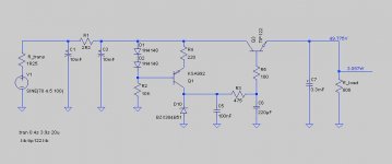
and that the regulated FE supplies looked something like this:

Would that make the "rumble filter" between the FE and OS stages (R11/C6 in first schematic) unnecessary? Or is it not about rail noise to start with?
Thanks,
Jeff.
and that the regulated FE supplies looked something like this:
Would that make the "rumble filter" between the FE and OS stages (R11/C6 in first schematic) unnecessary? Or is it not about rail noise to start with?
Thanks,
Jeff.
Attachments
huh
it seems that my ZMengrish and your Irish aren't on same page today
why "rumble"
that term is , at least for geezer as moi , strictly turntable area
if you have series reg for FE - better to think about elevated rails - enough higher than OS rails , than thinking about unnecessary additional pre-reg filters
if that is what you're talking about
Rumble filter == high pass filter. And yeah, I'm old enough to have started with rotation vinyl. 😉
But I'm asking about the RC filter between the FE and the OS. Is that for PS noise rejection in the FE, or something else?
FE rails regulated at 50V; OS rails unreg at 44V. Separate transformers.
Thanks!
But I'm asking about the RC filter between the FE and the OS. Is that for PS noise rejection in the FE, or something else?
FE rails regulated at 50V; OS rails unreg at 44V. Separate transformers.
Thanks!
aha , my old eyes ..... didn't read R11/C6 part
R11 is sort of stopper/dumper part in FE output , limiting current just in case
C6 is necessary as DC decoupling part
why you're asking for parts , you put in schematic , in first place ?
R11 is sort of stopper/dumper part in FE output , limiting current just in case
C6 is necessary as DC decoupling part
why you're asking for parts , you put in schematic , in first place ?
This evolved from the BA2. I'm just trying to figure out if the RC filter is an appendix or a kidney at this point (ie: vestigial or not).
Papa states "You will note that RC networks appear between the output node of the front end and the input of the output stage. C203 rolls off the low frequency response at about 2 Hz..."
If I didn't need the low frequency roll-off, I could replace the single level-shifting capacitor (C1) with one on each side (like the F4). That speaks to my love of symmetry....
- Status
- Not open for further replies.