I mentioned it because it's an interesting example of how
things work - the output device is actually driven by the
voltage across the resistor with current provided by the
input JFET. This voltage has been bootstrapped by the
output, so now it depends on the gain of the output
device.
So you have to ask yourself - is this really a follower?
😎
Michael,
Is he saying that ground resistors R13/R14 in your schemtic is bootstrapping the Jfet front end, making it a ccs for the output fets. Is th output fet being operated common gate? What resistor is bootstrapping the output? THere is so much going on in this "simple" little amp. One thing that has helped is reading a post by Nelson in which he states that the fets have no idea whether they are being operated common source or common drain. It helps you see that there are in fact, copies of the signal everywhere in this thing.
R11/12. I believe NP is applying the term bootstrap to the positive feedback in this case.
Strike the bit about "making it a ccs for the output"
The salient point for for me was "The output device is actually driven by the
voltage across the resistor with current provided by the
input JFET."
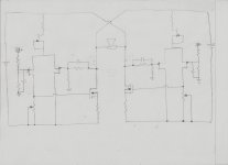
Now, go back to the diagram I originally posted and look at it again.
Strike the bit about "making it a ccs for the output"
The salient point for for me was "The output device is actually driven by the
voltage across the resistor with current provided by the
input JFET."
Now, go back to the diagram I originally posted and look at it again.
Last edited:
I believe NP is applying the term bootstrap to the positive feedback in this case.
Then, some folks in this here mall may argue for weeks whether it's the driving voltage or the input JFET current that's bootstrapped.


R11/12. I believe NP is applying the term bootstrap to the positive feedback in this case.
Strike the bit about "making it a ccs for the output"
The salient point for for me was "The output device is actually driven by the
voltage across the resistor with current provided by the
input JFET."
Now, go back to the diagram I originally posted and look at it again.
indeed, that quote by Nelson was what really made the penny drop for me too. i only had theories of how circlotrons worked before that and your cut is the perfect amp to toy around with as its a relatively pure example
I think the floating nature of the circlotron accounts for a good bit of its scary reputation. Ground orients us, like gravity, and when you take it away things start looking wonky.
To understand the circlotron, you must first understand the circlotron.
To understand the circlotron, you must first understand the circlotron.

Got to get BA-3 and BA-2 up and runnig this weekend. Circlotron gets built next weekend. I better get a lot of salt😀
yep, it certainly helped a great deal more than anything else, to just pick it up, dial in a lowish voltage and let it rip.
It's funny, I'm at least partially responsible for the fallacy that the AFC output stage doesn't have voltage gain. Then NP helped me see the light. And now, I find myself needing to prove that it does. So I'm really arguing against... myself. 🙂
By way of vindicating / redeeming myself, just a few hours ago I completed a copy af an actual single-stage circlotron with both current and voltage gain.
As currently built, voltage gain is around 15 dB and 1 Watt distortion is around .05%. If this confirmation gives anyone out there the confidence to move forward then I wish you godspeed.
If there's interest in a short write-up, I could do that. 🙂
The is revelation only makes me feel better about this circlotron thingy. Any write-up would be nice, but hopefully it will take a while as I want to conquer this beast without too much help. I looked at everything again while listening to "Thick as a Brick" and it didn't help any. Just can't get the concept to sink in😀
Question. You said earlier that R11/12 were doing the bootstrapping duties. I have read up on this bootstrapping thing and most of what i have found uses capacitors as part of the circuit. The Ba-2 serves as a beautiful example of the current type. Next i found that a different kind of bootstrap was used in the F4, this involved a voltage rather than a current. Now we have this Circlotron thingy introducing yet another type, and if that wasn't enough, there are no caps. Any reading material to help with this. All About Electronics just touches on the subject. Sorry if this post is incoherent, Rodney Strong is visiting tonight and he is such a wonderful guest
Question. You said earlier that R11/12 were doing the bootstrapping duties. I have read up on this bootstrapping thing and most of what i have found uses capacitors as part of the circuit. The Ba-2 serves as a beautiful example of the current type. Next i found that a different kind of bootstrap was used in the F4, this involved a voltage rather than a current. Now we have this Circlotron thingy introducing yet another type, and if that wasn't enough, there are no caps. Any reading material to help with this. All About Electronics just touches on the subject. Sorry if this post is incoherent, Rodney Strong is visiting tonight and he is such a wonderful guest
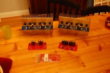
Here is what I have gotten done today. Crippled F4 with IRF(another set awaiting Laterals 2sk1058/sj213), BA-2 FE, BA-3 FE, and twin sister BA-3B on deck. Realized I ordered TO-220 instead 247 mica insulators so know listening this weekend. I will finish everything but mounting, so next weekend will be listening time and beginnings of circlotron experiments. I will try Jfet FE plus 2sK2013 output for what i hope is simple BA-C FE in the makings. A couple pre-reality ideas include singe differential pair used as phase splitter driving both sides and two diif pair with one driving each side with feedback like Ba-2. These are either decent ideas or a revelation of how little i know. Based on the thread, I am sticking with the latter. Soon enough we will find out. I have some extra fets to sacrifice to the BA gods!
Attachments
Any write-up would be nice, but hopefully it will take a while
Don't worry, I'm slow.
R11/12. I believe NP is applying the term bootstrap to the positive feedback in this case.
Strike the bit about "making it a ccs for the output"
The salient point for for me was "The output device is actually driven by the
voltage across the resistor with current provided by the
input JFET."
Now, go back to the diagram I originally posted and look at it again.
I think something may have clicked about the bootstrap and how it drives the output. The voltage that is seen across R11/12 affects the Vgs of the Jfet, manipulating/ changing the transconductance and ultimately the current at it's drain, which in turn affects the voltage at the gate of the mosfet. So, in essence, the Vdrop across that resistor does drive the output in a twisted circlotron sort of way.
Last edited:
consider me dumb 
but I can't see any improvement over "classical" SUSY stage ;
one diff pair with two outputs
?
but I can't see any improvement over "classical" SUSY stage ;
one diff pair with two outputs
?
Yep. Susy was exactly what i was thinking about staring at this thing. A different PSU for the FE would allow single diff pair and susy, but seems overdone for FE concept, much like this idea. Definitely not Zen like.
off course - I meant on "SUSY - one LTP with two pair of outputs"
for me - more elegant , more balanced ;
if balanced is goal ....
for me - more elegant , more balanced ;
if balanced is goal ....
- Status
- Not open for further replies.
- Home
- Amplifiers
- Pass Labs
- BA-C