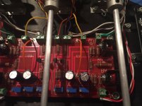
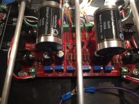
Tight fit! BA3 PSU
Here is the layout for my BA3 preamp RAW PSU. Power goes first to green "always on" control board which will switch the preamp and 2 power outlets with a 10A relay. These outlets will be used for the phono stage and power amp so with the push of a button the entire amplification chain will power on and off.
Preamp raw psu is composed of the AC line filter (silver box to be mounted on a sideways bracket), nice polish toroidal and RAW PSU board.
RAW DC will then go via umbilical cable to preamp case with Salas SSLV regulators, relay based attenuator and control board. More pictures later.

It's not as cool as seeing the real thing, but -
Thanks for posting the pics.
Do I understand correctly that the XP10 is DC coupled and so no output caps?
nash
Ah, Jos van Eijndhoven attenuator, nice!
It is quite a neat design indeed!!
I have isolation transformers on the inputs of my F5. Does this mean I could eliminate the output caps on the BA3-FE which is feeding it, or am I way off in my thinking.
transformers do not perform well when DC current flows.
If your BA3-FE has significant DC on it's output, then you must prevent that interfering with the isolation transformer.
If your BA3-FE has significant DC on it's output, then you must prevent that interfering with the isolation transformer.
transformers do not perform well when DC current flows.
If your BA3-FE has significant DC on it's output, then you must prevent that interfering with the isolation transformer.
In Bill Whitlock's book on Transformers he mentions that transformer cores can become magnetized with even small amounts of DC flowing. Unsure what "small" meant I spoke with Dave Hill, general manager at Jensen Transformers and posed this very question.
I explained that in our SS preamps such as the BA3 pre we could have around 100mv DC offset at start up tapering down to under 10mv when fully warm and would that cause any problem with their input transformers like the JT11P1 if I used it just like Kevin has as the input to my power amp. He said that would work very well but asked that I should use their damping network of 13k resistor and 680p film cap like in their schematics. He said that iron cores tend to get magnetized very quickly but the nickel based cores tend not to. Even if they get slightly magnetized they will start losing their magnetism as the DC is reduced. I asked that if I am not monitoring my DC offset and something goes haywire then what, and he said that you will hear the sound distorting especially at the low end.
I felt quite satisfied with his response.
nash
Alright Nash, despite a bit of anxiety over doing this, I pulled the output caps on the BA3-FE. I think it's a significant improvement from top to bottom. Everything seems to have a bit more clarity and texture...like a bit of haze was removed that I didn't know was there.
Of course before doing this I measured DC offset. I never realized how much and how continuously it drifts, but then I never had a instrument as sensitive as the Keithley 2015 to measure it with either. the best I can get is a swing between + and - 5mv.
Of course before doing this I measured DC offset. I never realized how much and how continuously it drifts, but then I never had a instrument as sensitive as the Keithley 2015 to measure it with either. the best I can get is a swing between + and - 5mv.
Pass DIY Addict
Joined 2000
Paid Member
Kevin: What type of caps were you using on the output of your BA-3? I looked back through this thread and found some images you posted of your boards and it looks like the spot for the film cap was open.
Pass DIY Addict
Joined 2000
Paid Member
Thanks for the additional info, Kevin. I have Obbligato Gold film and foil caps in mine - I haven't tried removing them yet. It's been a while since I looked at the offset, perhaps it is time to look again...
Thanks for the additional info, Kevin. I have Obbligato Gold film and foil caps in mine - I haven't tried removing them yet. It's been a while since I looked at the offset, perhaps it is time to look again...
Are you also running input isolation transformers in your amp?
Pass DIY Addict
Joined 2000
Paid Member
No, I don't have any isolation which is why I haven't done anything with this yet. Having just recovered from a power supply failure in an amp (cap went bad, driving voltage to the ground plane, blowing fuses, but protecting the amp circuit), I'm a bit shy to remove safety barriers.
Can you connect to output of BA3 a balanced converter type DRV134 or That. It is to connect to a power amplifier with balanced inputs.
www.atmstore.es
Twitter: @atm_store
www.atmstore.es
Twitter: @atm_store
So I removed the output caps on my BA3 preamp (was using elna silmic electrolitics) and after careful bias and dc offset adjustments I have less than 10mV offset in each channel.
Connected to my F4 amplifier (which has 2 capacitors which effectively block DC) I got a huge improvement in the sound quality.
I can notice more detail and a more airy sound with. Bass is a bit tighter too. Since I will only use it with my F4 I will keep it this way.
Connected to my F4 amplifier (which has 2 capacitors which effectively block DC) I got a huge improvement in the sound quality.
I can notice more detail and a more airy sound with. Bass is a bit tighter too. Since I will only use it with my F4 I will keep it this way.
I got a huge improvement in the sound quality.
I can notice more detail and a more airy sound with. Bass is a bit tighter too.
That's what I'm saying!
I think you can just use an input transformer like the Jensen JT-11P-1BN.
in any case it will output transformer.
www.atmstore.es
Twitter: @atm_store
one only needs ONE dc blocking capacitor in any signal route.So I removed the output caps on my BA3 preamp (was using elna silmic electrolitics) and after careful bias and dc offset adjustments I have less than 10mV offset in each channel.
Connected to my F4 amplifier (which has 2 capacitors which effectively block DC) I got a huge improvement in the sound quality.
I can notice more detail and a more airy sound with. Bass is a bit tighter too. Since I will only use it with my F4 I will keep it this way.
If two are fitted then choose that one that gives the better performance.
Using two does not stop the signal getting through. But it does change the roll-off frequency.
eg.
The Source has an output DC blocking cap of 2u2F
The receiver has a DC blocking cap of 4u7F and an input impedance of 10kohms.
The F-3db of that arrangement will be 2u2F+4u7F into 10k and comes out at 10.6Hz
If you bypass the 2u2F at the Source output then the f-3db becomes 3.4Hz
The difference in bass will be noticeable with most speakers.
- Home
- Amplifiers
- Pass Labs
- BA-3 As Preamp

