Ok, thanks.
Have you compared the THD results of both options (reduce input gain , reduce output gain) or the mix of the two to find the optimal solution?
Fab
Do you Know somewhere or another audio forum where they have experimented to get the response to my question...
Thanks
Fab
How much change in gain?
Back in post 711, Juma suggested changing the values of R5-R7 to lower the gain.
The image below shows the values he suggested.
Can someone please tell me how much the gain is reduced compared to the gain using the standard value resistors?
Thanks...
Back in post 711, Juma suggested changing the values of R5-R7 to lower the gain.
The image below shows the values he suggested.
Can someone please tell me how much the gain is reduced compared to the gain using the standard value resistors?
Thanks...
Attachments
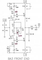
So the gain is about 1/4 of the original design.
Is there a downside to reducing the gain this way?
Is there a downside to reducing the gain this way?
BA-3 pre gives noise
Hi All,
First of all, I rebuild my F5 to F5 turbo v2, but ran into a problem.
My F5 Turbo V2 is silent..... Speaker connected. although when my pre-amp is connected with the F5 it hums loud, there is also a little bit of sharpness in it.
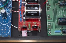
My pre-amp is a BA-3 FE stage powered by a PSUboard v3 @24V. I made a star ground, and installed a relay volume control. Lite audio V02.
BA3 is biased at 1V over R10-R11 and about 20mV DC (measured before CAP and gnd) over R12 there is no DC. I can not figure out where this hum comes from. The interconnects do not interfere, cables only connected at the power-amp gives no hum. I think it's a Ground-loop triggered by the Pre-amp. today I did tried several things without any luck.
- re-solder internal wires and changed interconnects. still humming.
- disconnect interlinks, nu hum
- replace volumecontrol and connect interconnects. reconnect input and output to RCA socket.
- finally I re-solder the connections on the BA-3 beard (input and output).... No hum on left channel. But when powering up BA-3 the hum appears again.😱😡
The B1 was in and I used this one also to check whether there is a Hum.... And it was..🙁
Since I was testing, I only connected the Main input and output. So try to look trough the Spagetti😉
Any of you Experts have an idea where to look?
All help is appreciated.
Nils
Hi All,
First of all, I rebuild my F5 to F5 turbo v2, but ran into a problem.
My F5 Turbo V2 is silent..... Speaker connected. although when my pre-amp is connected with the F5 it hums loud, there is also a little bit of sharpness in it.
My pre-amp is a BA-3 FE stage powered by a PSUboard v3 @24V. I made a star ground, and installed a relay volume control. Lite audio V02.
BA3 is biased at 1V over R10-R11 and about 20mV DC (measured before CAP and gnd) over R12 there is no DC. I can not figure out where this hum comes from. The interconnects do not interfere, cables only connected at the power-amp gives no hum. I think it's a Ground-loop triggered by the Pre-amp. today I did tried several things without any luck.
- re-solder internal wires and changed interconnects. still humming.
- disconnect interlinks, nu hum
- replace volumecontrol and connect interconnects. reconnect input and output to RCA socket.
- finally I re-solder the connections on the BA-3 beard (input and output).... No hum on left channel. But when powering up BA-3 the hum appears again.😱😡
The B1 was in and I used this one also to check whether there is a Hum.... And it was..🙁
Since I was testing, I only connected the Main input and output. So try to look trough the Spagetti😉
Any of you Experts have an idea where to look?
All help is appreciated.
Nils
Attachments
What are the noise measurements at the outputs?
Shorted input.
Open input
one interconnect
two interconnects
short one interconnect
short other interconnect
Short the two interconnect barrels together
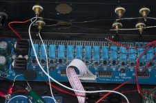
Why have you got so many single wires inside?
Shorted input.
Open input
one interconnect
two interconnects
short one interconnect
short other interconnect
Short the two interconnect barrels together
Why have you got so many single wires inside?
What are the noise measurements at the outputs?
Why have you got so many single wires inside?
Hi Andrew,
How to measure noise with DMM? And the thought for single wires was to use a star ground. Connect all RCA gnd to the star-gnd and signal to the input.
should I use shielded cable. Once read that CAT5 mono wire is a good internal connection. I use silver plated CU.
Nils
A DMM set to 199.9mVac measures hum+noise down to 0.1mVac.
Variations in that noise voltage tell you whether the most recent wiring modification is an improvement over what came before.
you may find that each modification only reduces the noise voltage by a few percent, but when all are combined you get a significant noise attenuation. You can also use the "it got worse" results to ensure you don't incorporate a bad modification.
If your DMM does not have a 199.9mVac scale, then go out and buy a cheap DMM that does have this facility.
All circuits are formed from a LOOP that passes current from Source back to Source.
The current flows out from the source and returns back to the source.
This is inherent in ALL circuits. There are no exceptions.
This means that WE have to use TWO wires/traces to pass current from and back to a source. I call them Flow and Return.
Using this connecting philosophy I find that I don't need any "grounds". It is almost all Flows and Returns.
a LOOP is an aerial. place a loop inside your amplifier and pass a varying current around the LOOP. That LOOP emits radiation.
Place a loop in a circuit. Apply a changing electromagnetic field around or near the loop. The loop will pass current. This is interference current.
Big loop area makes good aerials. Small loop area makes bad aerials.
ALL your Flow and Return PAIRS should be laid out as close coupled wires/traces to minimise LOOP AREA. You can use parallel pairs for small loop area, or a bit better use twisted pairs for small loop area and cancellation of interference, or screened twisted pair for even better attenuation of interference. Just about the same performance can be got by using coax.
Last edited:
Thanks for the clear explanation.
My DMM has that function as far as I can tell.
In respect to loops, twister pairs or coax will be installed on all connections.
another NOOB question 0,1mVac is better than 100 mVac I presume?!?😕
Thanks again,
Nils
My DMM has that function as far as I can tell.
In respect to loops, twister pairs or coax will be installed on all connections.
another NOOB question 0,1mVac is better than 100 mVac I presume?!?😕
Thanks again,
Nils
if the output noise is <=0.1mVac then you won't hear any hum nor noise at the normal 87dB speaker.
even 0.5mVac may be tolerable.
But >1mvac is more than I would tolerate.
10mVac would be a disaster.
100mVac has no definition in my fault finding guide.
even 0.5mVac may be tolerable.
But >1mvac is more than I would tolerate.
10mVac would be a disaster.
100mVac has no definition in my fault finding guide.
did a short measurement,
output is fluctuating between 0,2 and 0,1 mV ac. Hope this is ok for starters.
What is the exact place for setting up the BA-3.
I did set 1 V dc over R10 and R11. And the offset measured before the Cap and Gnd
don't think the problem lies here because the hum is also present when there is no power on the system!
I'm a little last here
I will try to measusr the noise (Andrew) with different settings.
I am trying to bias mine now.
It's taking a lot of turns of p1 and p2….I've gone about half way on the pot and still no voltage on R10/11. Or R9.
I am using 1K pots and the fairchild mosfets. Mosfets are cold, Jfets are getting warm. I've verified the BA-3 board is seeing voltage from the PSU.
Is this normal?
Finished my BA-3 FE at the weekend.
Mosfets are Fairchild.
Jfets has approximately 8mA idss.
Rail voltages are 24V.
P1-P2 1K trimpots.
P1-P2 set to zero (reading from across caps)
P3 set to mid position (reading from R3-R4)
Inputs shorted
Fired up with DBT. Bulb glows bright for 2 seconds then dims completely.
Connected to full mains.
Rail voltages are stable at 24V.
Problem is I can't get any reading across R10-R11. I'm almost middle of P1-P2. But there is no voltage across R10-R11.
Jfets Drain to ground readings are apprx 23-24V
Jfets Source to ground readings are apprx 60mV
I turned off and zeroed trimpots (afraid to cook something)
My problem is pretty much same as Hikari's problem. But as I read it solved when inputs shorted. My inputs are already shorted. but still no voltage across R10-R11.
Any idea?
😕
unplug and make sure all the capacitors are discharged.
Set p1 and p2 to zero.
measure resistance of p1 and p2.
set p1 and p2 to halfway.
measure resistance of p1 and p2.
set p1 and p2 to maximum.
measure resistance of p1 and p2.
Set p1 and p2 to zero.
measure resistance of p1 and p2.
set p1 and p2 to halfway.
measure resistance of p1 and p2.
set p1 and p2 to maximum.
measure resistance of p1 and p2.
Starbender - turn the pots more... You are not introducing enough resistance to get the mosfet to turn on.
@AndrewT;
I'll measure P1&P2 tonight.
@Jim;
I'm thinking the same thing 😉
But I don't want to risk anything. I'll try to increase resistance. As I read Fairchild mosfets needs 4V to turn on.
I'll measure P1&P2 tonight.
@Jim;
I'm thinking the same thing 😉
But I don't want to risk anything. I'll try to increase resistance. As I read Fairchild mosfets needs 4V to turn on.
- Home
- Amplifiers
- Pass Labs
- BA-3 As Preamp