I received this amp for repair.. Obviously everything is OK. It started for a few seconds, than in protect. Checked the audio banks, one works good, the other has problems to build up waveforms. I don't now this drive board. Is there also irs21844s inside? Mosfets measures all OK. The output from the drive board is buffered.
Attachments
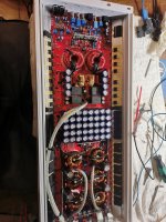
I correct myself.. Audio part is also OK. The amp starts sometimes for a few seconds, all signals are good, then in protect again. If i apply remote again, then it goes in protect directly, but tries to build up square wave. Rail seems OK with about 50 volt
If I heat up the area around the ps drive board, the amp stays longer on.. Maybe cold solder joint.
Do both halves produce clean audio before it goes into protect?
Is there any significant DC offset on either half of the amp?
Is there any significant DC offset on either half of the amp?
There is no dc offset, but poor audio signal. At this amp, Iam not sure where I can find secondary center.. Seems like full bridge design
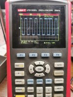
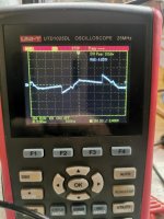
Here a picture from the output
Here a picture from the output
Attachments
Last edited:
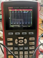
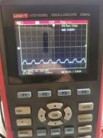
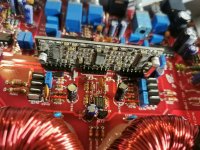
The center row of the audio drive board has +15,-15 v. The last pin is for the protection circuit. It's slowly rising to 2v, then the amp shuts down. And I have this disorted audio signal on both banks.
Is the protect pin receiving a protect signal or is the protect signal coming from the driver board?
If it's receiving the signal, can you defeat it?
If it's receiving the signal, can you defeat it?
So, at first, the audio output is clean. My rca cable from my signal generator was broken. I cut pin 6 in the half. The half on the audio drive board has 5v, the half on the mainboard has 0v if I connect them again, it's slowly rising to 2v and protect again. So it must come from the audio drive board.
The audio signal stays OK, no offset, or disorted signal. The pin 6 at the drive board stays at 0v,then a few moments later it rapidly goes up to 5v
Can you determine what's driving pin 6 on the main board?
What does pin 6 on header go to on the driver board?
Have you been able (using the pin configuration, including supply pins) determine what the center IC is?
What does pin 6 on header go to on the driver board?
Have you been able (using the pin configuration, including supply pins) determine what the center IC is?
I have to check, but I don't know what the center ic is doing. But I just figured out, if I blow air on the drive board, the 5v drops immediately to 0v. I can repeat it several times.
The pin 6 on the drive board goes to a smd transistor FR 36 Sot323 collector. Base and emitter has 5v. So maybe the transistor is leaking
I replaced the transistor with a mmbta4401. Now I have 5v all the time at the collector. I soldered the bridge at Pin6, voltage is now 1.6v. Amp still not in protect.. I will let it idle for a while.
I damaged one drive ic, damn.. But the amp was still going in protect.. I have to order drive ics now.. Iam not sure, how to figure out, if it is a 2092s?
Use the pin configuration. The high-side supply is typically obvious as is the connection to the negative rails and the output pins...
so replaced both irs2092. Amp works as before. If i heat the replaced FR transistor, the amp goes in protect directly.
Base:2V
Emitter: 5V
Collector 1,5V
Collector goes to pin 6
If i heat up, i cant see voltage rising. I expect, its exactly at the threeshould limit
Base:2V
Emitter: 5V
Collector 1,5V
Collector goes to pin 6
If i heat up, i cant see voltage rising. I expect, its exactly at the threeshould limit
- Home
- General Interest
- Car Audio
- B2 MA 6000.1