Thanks Zen Mod: I hope I'm following you correctly...
PCB in left channel 1.7 ohms full counter clockwise; 48.7k ohms full clockwise
PCB right channel 0.6 ohms full counter clockwise; 49.4k ohms full clockwise.
RCA ground/hot:
input 2 white 48.9k ohms; red 49.4k ohms (fixed)
input 1 no reading white or red.
Need to reflow solder at barrel and tab input 1?
Thank you
Craig
everything sounds logical, so input and pot are correctly wired
more pics time
About half way through on the complete store kit and I’m getting 9 volts instead of 24. Not sure why. Am I missing something obvious?
Well, you need to place your black lead wire in one of the ground connection. Then place the red lead wire where the black is currently, and you should read 9.25 volts.
Your component assembly is correct, it is just the way you measure it.
Yves
Hi, there is also a specific thread about a balanced version of the B1 Nutube. I don't remember his name, but this member did a lot of deep tests and measurements on this particular configuration. Other than this, I used output transformers to get balanced signal from se with good results to my ears.
Gaetano
Balanced B1 with Korg Triode
Building the Pete Millett Korg Nutube Balanced Preamp
Another ACA and B1 happy person
Hello all
So even having a miserable electronics understanding type i have yet managed to build the B1 and it's working!
Now i am very happy with ACA and B1, right now Jazz is a pleasure to listen to 🙂
Thank you all, thank you Mr Nelson!
Without all the knowledge, effort and information you all share here i would never get the nerves to attempt these builds!
My sincere gratitude.
.... now i have to take a deep breath and look at the F5 build 🙂
Attachments
Last edited:
B1 success
Zen Mod pointed me in the right direction.
Bad solder joint.
Music playing as I write...
Craig
everything sounds logical, so input and pot are correctly wired
more pics time
Zen Mod pointed me in the right direction.
Bad solder joint.
Music playing as I write...
Craig
Is it okay to replace all six of the 10uF electrolytic capacitors with polypropylene capacitors of the same value in the kit version of the B1 preamp? It sounds wonderful now and is likely to be even better with good capacitors. I just don’t know if they can be substituted in all circuits. Any suggestions on good capacitors that don’t cost a fortune?
use Silmic 10uF for each position and bypass each with 1uF solid cap of your choice
for anything better than that you'll need to pony up enormously
for anything better than that you'll need to pony up enormously
I realize the Silmic II is supposed to be an audio grade cap but is it considered as good as a polypropylene cap? I was under the impression that poly caps always sound better. Does the circuit require polarized caps or am I free to choose otherwise as long as the specs are the same?
You can chose as you want... and the good news is you don't even have to stick to these values, so can save some money. Use the search function in this thread: I did replace the 6 DC blocking caps with PPP ones and reported extensively. On this mod... and other mods.
ZM's tip will of course be less expensive than PPP caps, and have a better footprint, but chosing values cleverly helps a lot saving money and making things fit. All in my posts, and also thanks to Papa's and ZM's help...
Enjoy music
Claude
ZM's tip will of course be less expensive than PPP caps, and have a better footprint, but chosing values cleverly helps a lot saving money and making things fit. All in my posts, and also thanks to Papa's and ZM's help...
Enjoy music
Claude
use train if you want ...... or plane or any sort of polarized or non polarized cap you want
you asked for advice, I gave you mine
now try every combination you can think of, then leave in what you prefer by hearing...... not by reading what anyone sez its best
🙂
you asked for advice, I gave you mine
now try every combination you can think of, then leave in what you prefer by hearing...... not by reading what anyone sez its best
🙂
Thanks. I’ll research your posts. I’m obviously no technician. Since you replaced the caps with polys I presume there’s no need for DC blocking caps. Does that mean the only reason they were selected and provided in the kit was expense related?
use train if you want ...... or plane or any sort of polarized or non polarized cap you want
you asked for advice, I gave you mine
now try every combination you can think of, then leave in what you prefer by hearing...... not by reading what anyone sez its best
🙂
Zen Mod, I much appreciate your reply and it certainly appears a good suggestion. The gist of my original post was that I’m interested in replacing electrolytic with polys. Your response provided good information but didn’t exactly address my question. I do appreciate your response and didn’t mean to get under your skin in any way. Best regards.
I realize the Silmic II is supposed to be an audio grade cap but is it considered as good as a polypropylene cap? I was under the impression that poly caps always sound better. Does the circuit require polarized caps or am I free to choose otherwise as long as the specs are the same?
Wayne performed some tests on the Silmics a few years ago and decided
that they were about as good for our purposes. However, I am told that
their manufacturing has altered, and the tests have not been run again.
Currently I am still working with the NOS inventory.
Thanks. I’ll research your posts. I’m obviously no technician. Since you replaced the caps with polys I presume there’s no need for DC blocking caps. Does that mean the only reason they were selected and provided in the kit was expense related?
The polypropelene caps will still block DC. Any cap will. And, yes, I think these are needed. There is DC coming from the power supply into the gate of the input JFETs, and that would otherwise bleed back out to the source. (I learned about that not long ago. I'd always thought of the caps as blocking incoming DC. But of course it goes both ways!)
Besides the Silmics, the Nichicon KZs are supposed to be among the best electrolytics out there for audio. They're about the same price. Check out this site, which I've found quite useful.
As Claude said, the big issue is getting the caps wedged in there. There is very little space, and good 10uF film caps do tend to be large (as well, as ZM said, expensive).
If you do try it, let us know how it comes out. I've thought about doing the same thing for my build.
Zen Mod, I much appreciate your reply and it certainly appears a good suggestion. The gist of my original post was that I’m interested in replacing electrolytic with polys. Your response provided good information but didn’t exactly address my question. I do appreciate your response and didn’t mean to get under your skin in any way. Best regards.
accent of what I wrote is to inform you that any type of cap will do electrical job (block DC, conduct AC) and that you try any , and leave one which you like most
do not worry, I'm not too sensitive 🙂
Another successful build reporting in.
First my thanks to NP and all those that put this kit together for yet another electronics newbie.
All test values are nominal and for two days I did not have a bit of microphonic problem only very nice sound but with a couple of things I will get to.
Then microphonics started, out of nowhere in near absolute silence. No music playing no noise in the room or elsewhere. I had blue tac under the board from the get go but have now tamed the problem with a blue tac brick on the face of the tube.
As far as tube bias I think I prefer about 10.5 volts at tp7 and 8 but that is subject to change.
I do perceive that the soundstage image is slightly left of centre or that there is a hole to the right and slightly behind the right speaker. This is most prominent as I lower the bias voltage??? At 10.5 volts it is least noticeable, the speaker waltz has commenced.
After reading cccochran 5436-38 and the reply by zen mod 5437-42 I did some poking around and found some things that maybe someone can explain to me?
RCA ground to hot R 8.3 ohms L 8.0 ohms both fixed
PCB R fully counterclockwise 0-12.8k-minus 8.0 ohms fully clockwise
PCB L fully counterclockwise 0-13k-0 fully clockwise.
Thanks also to the most experienced of this group for all the advice and help to us the least experienced, please keep it coming.
Voltage issues T7 and T8
I have completed my build but have been unable to get the correct voltages out of test point 7 and 8
T7 and T8 are around 20 volts and I can adjust T8 to 10 volts and T7 to 19 volts
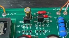
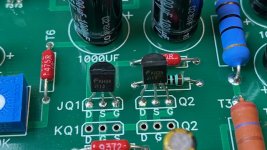
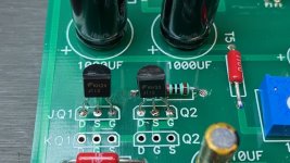
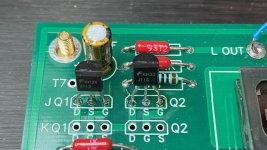
I notices the JFET from Q1 and Q2 are FKH23 J113, FKH34 J113 FKH35 J113 and FKH33 J113 and wonder if they are installed correctly.
I am pretty sure I kept the bags separated. See attached image for installation. any help would be appreciated
I have completed my build but have been unable to get the correct voltages out of test point 7 and 8
T7 and T8 are around 20 volts and I can adjust T8 to 10 volts and T7 to 19 volts
I notices the JFET from Q1 and Q2 are FKH23 J113, FKH34 J113 FKH35 J113 and FKH33 J113 and wonder if they are installed correctly.
I am pretty sure I kept the bags separated. See attached image for installation. any help would be appreciated
Attachments


Last edited:

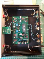
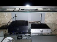
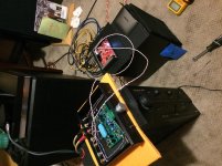
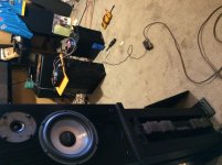
Build photos
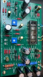
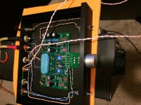
Sorry forgot to show photos earlier, looks much like everyone else’s.
You can see where i wired my Schiit Modi DAC direct for the time being. Also you might be able to see my power supply on an extension cord. The ps was causing a rapid ticking through the system so I found a quiet supply elsewhere in the room.
Still hoping someone can shed some light on the reading commented on in an earlier post. Thanks in advance.
Attachments
- Home
- Amplifiers
- Pass Labs
- B1 with Korg Triode