for preamps , you can try cheap (if you already have them laying around) solution - neon balast chokes .... not likely to saturate with moderate DC
and - do not bother with few mH ..... that's appropriate only for CLC
and - do not bother with few mH ..... that's appropriate only for CLC
for preamps , you can try cheap (if you already have them laying around) solution - neon balast chokes .... not likely to saturate with moderate DC
and - do not bother with few mH ..... that's appropriate only for CLC
Ok.
How about this one:
Hammond 159Y: 600 mH, 11 Ohms, 750mA rating
Would it make sense to use 2SK330/2SJ105 for this version of the B1?
If you already have those in your stash of parts, then yes.
It will in some ways depend on what you intend to drive.
I prefer something that is as universal as possible ie can drive both difficult and easy loads.
So for me at 12Vds, I'll be looking to parts with Idss levels of 16mA to 20mA (operating current figure will drop once you add source resistance), so I'll personally want the the to92 k270/j74 device with higher power rating.
You probably don't need what I want, and if you did you could consider paralleling parts (assuming you have an abundance of those laying around)
Last edited:
well , buffer with 2SK330/2SJ105 is on the verge to be called a buffer
maybe , if using triples , at least
maybe , if using triples , at least
Well, I just have no 2SJ74 anymore, and do not know a good source for new ones. 2SK170 I still have a few. The LSK parts from the diyAudio store are actually a bit expensive.
and yes , spending that amount of money for piece of Mana from Heaven , certainly isn't reasonable

yup
I can just imagine his green , making his shunt reg ......... packed with general unobtanium

I can just imagine his green , making his shunt reg ......... packed with general unobtanium

I dont know why i got an idea to add 50ohm trimpot on my dcb1 xo output buffer (copying B1 rev2 for P102), where I'm using 2SK170 source follower 🙁 maybe i just read somewhere that upper jfet can be selected from higher Idss to get null dc offset. Currently i use 9.7mA for upper jfet and 9.5mA on lower one.
it's not powered yet, maybe less than 40% completed. I will test first 12dB filter than add second 12dB if required, at least the layout has spare space.
is this workable? or should i take out the trimpot?
it's not powered yet, maybe less than 40% completed. I will test first 12dB filter than add second 12dB if required, at least the layout has spare space.
is this workable? or should i take out the trimpot?
Attachments
I dont know why i got an idea to add 50ohm trimpot on my dcb1 xo output buffer (copying B1 rev2 for P102), where I'm using 2SK170 source follower 🙁 maybe i just read somewhere that upper jfet can be selected from higher Idss to get null dc offset. Currently i use 9.7mA for upper jfet and 9.5mA on lower one.
it's not powered yet, maybe less than 40% completed. I will test first 12dB filter than add second 12dB if required, at least the layout has spare space.
is this workable? or should i take out the trimpot?
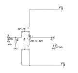
exact schematic of buffer ,please
Isn't this an active crossover?
If yes best to start a new thread
exact schematic of buffer ,please
I'm using one of posted schematic in B1 active xo thread (which seems get less interest) as my basic reference, but I try to incorporate with B4 feature (dip 8 switch for cut off freq and output attenuator, 6/12dB and bypass jumper).
my output buffer is exactly as attached file, with additional 50ohm trimpot before 330R output resistor
using B1 rev2 for my buffer based on original B4 will be quite expensive, so i'm trying to be creative
Attachments
Last edited:
Thanks ZM for the schematic, already saved it.
but wait, I'm a dumb man related to parts function (never enjoyed my EE class). There is no 1M resistor to output ground, same as attached file for another dcb1 xo schematic. So what is the benefit of removing the 1M resistor? Also if i remember correctly, 2SK170 will have around 50R resistance, so if output R is removed, what is the benefit of lowering output resistance?
but wait, I'm a dumb man related to parts function (never enjoyed my EE class). There is no 1M resistor to output ground, same as attached file for another dcb1 xo schematic. So what is the benefit of removing the 1M resistor? Also if i remember correctly, 2SK170 will have around 50R resistance, so if output R is removed, what is the benefit of lowering output resistance?
Attachments
and yes , spending that amount of money for piece of Mana from Heaven , certainly isn't reasonable
[emoji441][emoji351][emoji344]
[emoji106][emoji6]
Thanks ZM for the schematic, already saved it.
but wait, I'm a dumb man related to parts function (never enjoyed my EE class). There is no 1M resistor to output ground, same as attached file for another dcb1 xo schematic. So what is the benefit of removing the 1M resistor? Also if i remember correctly, 2SK170 will have around 50R resistance, so if output R is removed, what is the benefit of lowering output resistance?
what I sketched is , say , strict schematic for output buffer section , where each mV of output offset is important ; in any other position in your xover schematic , you don't need that trimpot , because dc offset is anyway blocked with capacitors
1M on output - it's not mandatory , but you can put it if you want
I'll not repeat myself about "importance" of series output resistor - that's idiotproof part , not having much with cable capacitance issues, as some ppl are involving ..... in fact , I wouldn't use it in that case , especially
also - output current is , anyway , limited by nature of part itself , so no current limiting safety issues
- Home
- Amplifiers
- Pass Labs
- B1 Rev. 2